LZP-00UA00 LedEngin, LZP-00UA00 Datasheet
LZP-00UA00
Specifications of LZP-00UA00


Related parts for LZP-00UA00


LZP-00UA00 Summary of contents
Page 1
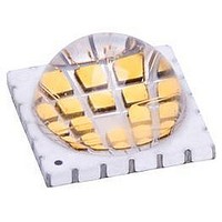
... High Radiant Flux Density 400nm Violet LED Emitter LZP-00UA00 Key Features Ultra-bright, compact 24-die, 400nm Violet LED Very high Radiant Flux density, 30 W/cm Small high density foot print, 12.0mm x 12.0mm x 6.7mm package Surface mount ceramic package with integrated glass lens ...
Page 2
... Typical Relative Spectral Power Distribution . . . . . . . . . . . . . . . . . . . . . . . . . . . . . . . . . 8 Typical Relative Dominant Wavelength Shift over Temperature . . . . . . . . . . . . . . . . . . 8 Typical Relative Radiant Flux . . . . . . . . . . . . . . . . . . . . . . . . . . . . . . . . . . . . . . . . . . . . 9 Typical Relative Radiant Flux over Temperature . . . . . . . . . . . . . . . . . . . . . . . . . . . . . . 9 Typical Forward Current Characteristics . . . . . . . . . . . . . . . . . . . . . . . . . . . . . . . . . . . . 10 Current Derating Curves . . . . . . . . . . . . . . . . . . . . . . . . . . . . . . . . . . . . . . . . . . . . . . . . 10 Emitter Tape & Reel Specifications . . . . . . . . . . . . . . . . . . . . . . . . . . . . . . . . . . . . . . . . 11 MCPCB Options Company Information . . . . . . . . . . . . . . . . . . . . . . . . . . . . . . . . . . . . . . . . . . . . . . . . . . 14 Table of Contents 2 LZP-00UA00 (R.1.6 – 110523) ...
Page 3
... Radiant Flux Maintenance (RP70%) at 25,000 hours of operation at a forward current of 700 mA per die. This projection is based on constant current operation with junction temperature maintained at or below 110°C. Product Nomenclature Soak Requirements Standard Time (hrs) Conditions 168 85°C/ +5/-0 85 Accelerated Time (hrs) Conditions n/a n/a LZP-00UA00 (R.1.6 – 110523) ...
Page 4
... Forward Voltage Bins Table 4: Minimum Forward Voltage (V /Ch) Forward Voltage (V F [1, 700mA F (V) 20.64 4 Maximum [1,2] = 700mA F (mW) 12000 15000 Maximum Peak Wavelength (λ [ 700mA F (nm) 395 400 405 410 Maximum /Ch) F [1, 700mA F (V) 23.52 LZP-00UA00 (R.1.6 – 110523) ...
Page 5
... LEDs are not designed to be reverse biased. 4. Solder conditions per JEDEC 020D. See Reflow Soldering Profile Figure 3. 5. LedEngin recommends taking reasonable precautions towards possible ESD damages and handling the LZP-00UA00 in an electrostatic protected area (EPA). An EPA may be adequately protected by ESD controls as outlined in ANSI/ESD S6.1. Optical Characteristics @ T ...
Page 6
... Figure 4: Recommended solder mask opening (hatched area) for anode, cathode, and thermal pad. Note for Figure 4: 1. Unless otherwise noted, the tolerance = ± 0.20 mm. Ch. Pad Die + LZP-00UA00 (R.1.6 – 110523) Pin Out Color Function UA Anode Cathode UA Anode Cathode UA Anode Cathode UA Anode Cathode na ...
Page 7
... Reflow Soldering Profile Figure 3: Reflow soldering profile for lead free soldering. Typical Radiation Pattern 100 -90 -80 -70 -60 -50 -40 -30 -20 - Angular Displacement (Degrees) Figure 4: Typical representative spatial radiation pattern. 7 LZP-00UA00 (R.1.6 – 110523) ...
Page 8
... Figure 5: Relative spectral power vs. wavelength @ T Typical Relative Dominant Wavelength Shift over Temperature 5.0 4.0 3.0 2.0 1.0 0 Figure 6: Typical dominant wavelength shift vs. case temperature. 400 450 Wavelength (nm) = 25° Case Temperature (ºC) 8 500 100 120 LZP-00UA00 (R.1.6 – 110523) ...
Page 9
... I - Forward Current (mA) F Figure 7: Typical relative Radiant Flux vs. forward current @ T Typical Relative Radiant Flux over Temperature 1.2 1 0.8 0.6 0.4 0 Case Temperature (ºC) Figure 8: Typical relative Radiant Flux vs. case temperature. 600 800 = 25° 100 9 LZP-00UA00 (R.1.6 – 110523) 1000 120 ...
Page 10
... Voltage (V) f Current De-rating = 1.0˚ C/W = 2.0°C/W = 1.5˚ C/W = 3.0°C/W = 2.0˚ C/W = 4.0°C 100 Maximum Ambient Temperature (°C) + RΘ [Case to Ambient Thermal Resistance]. J-C C 25°C. C 125 150 = 150°C. J(MAX) LZP-00UA00 (R.1.6 – 110523) ...
Page 11
... MCPCB thermal resistance is based on tests conducted on a copper based SuperMCPCB from Bridge Semiconductor RΘ Lookup Table J-B Table 8: Typical MCPCB + = RΘ C-B + 0.1°C Typical Emitter + MCPCB RΘ [1] J-B 0.70°C/W Pin Out Ch. Pad Color Function UA 10 Anode Cathode UA 9 Anode Cathode UA 8 Anode Cathode UA 7 Anode Cathode LZP-00UA00 (R.1.6 – 110523) ...
Page 12
... LedEngin is committed to providing products that conserve natural resources and reduce greenhouse emissions. LedEngin reserves the right to make changes to improve performance without notice. Please contact Sales@ledengin.com Company Information or (408) 492-0620 for more information. 12 LZP-00UA00 (R.1.6 – 110523) ...