TCS3414FN TAOS, TCS3414FN Datasheet - Page 16
TCS3414FN
Manufacturer Part Number
TCS3414FN
Description
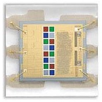
Photodiodes TRI Color Sensor LTD I2C 6 Pin ODFN
Manufacturer
TAOS
Type
Digital Color Sensorr
Datasheet
1.TCS3414FN.pdf
(40 pages)
Specifications of TCS3414FN
Photodiode Material
InGaN
Peak Wavelength
640 nm
Maximum Rise Time
300 ns
Maximum Fall Time
300 ns
Package / Case
DFN-6
Mounting Style
SMD/SMT
Product
Ambient Light Sensor
Lead Free Status / Rohs Status
Details
Available stocks
Company
Part Number
Manufacturer
Quantity
Price
Company:

Part Number:
TCS3414FN
Manufacturer:
NSC
Quantity:
430


TCS3404, TCS3414
DIGITAL COLOR SENSORS
TAOS137A − APRIL 2011
Timing Register (01h)
16
Copyright E 2011, TAOS Inc.
Reset Value:
INTEG_MODE
SYNC_EDGE
PARAM
PARAM
The TIMING register controls the synchronization and integration time of the ADC channels. The Timing
Register settings apply to all four ADC channels. The Timing Register defaults to 00h at power on.
FIELD
Resv
01h
Resv
7
0
BITS
5:4
3:0
3:0
7
6
SYNC_EDGE
Reserved. Write as 0.
Sync pin edge. If SYNC_EDGE is low, the falling edge of the sync pin is used to stop an integration
cycle when INTEG_MODE is 11. If SYNC_EDGE is high, the rising edge of the sync pin is used to
stop an integration cycle when INTEG_MODE is 11.
Selects preset integration time, manual integration (via serial bus), or external synchronization (SYNC
IN) modes.
Uses single, multipurpose bitmapped field to select one of three predefined integration times or set the
number of SYNC IN pulses to count when the INTEG_MODE accumulate mode (11) is selected.
NOTE: INTEG_MODE and TIME/COUNTER fields should be written before ADC_EN is asserted.
6
0
FIELD VALUE
FIELD VALUE
FIELD VALUE
0000
0001
0010
0000
0001
0010
0100
0101
1000
0011
0110
0111
00
01
10
11
INTEG_MODE
0
5
r
Table 5. Timing Register
www.taosinc.com
In this mode, the integrator is free-running and one of the three
internally-generated Nominal Integration Times is selected for each conversion
(see Integration Time table below).
Manually start/stop integration through serial bus using ADC_EN field in Con-
trol Register.
Synchronize exactly one internally-timed integration cycle as specified in the
NOMINAL INTEGRATION TIME beginning 2.4 μs after being initiated by the
SYNC IN pin.
Integrate over specified number of pulses on SYNC IN pin (See SYNC IN
PULSE COUNT table below). Minimum width of sync pulse is 50 μs. SYNC
IN must be low at least 3.6 μs.
NOMINAL INTEGRATION TIME
12 ms
100 ms
400 ms
SYNC IN PULSE COUNT
1
2
4
8
16
32
64
128
256
4
0
0
3
DESCRIPTION
2
0
PARAM
r
MODE
1
0
The LUMENOLOGY r Company
0
0
TIMING
Related parts for TCS3414FN
Image
Part Number
Description
Manufacturer
Datasheet
Request
R

Part Number:
Description:
Microcontroller Modules & Accessories TAOS Eval Module w/USB Interface
Manufacturer:
TAOS
Part Number:
Description:
Optical Sensor Development Tools TAOS Eval Module
Manufacturer:
TAOS

Part Number:
Description:
Industrial Optical Sensors Ambient Light Sensor SMBus
Manufacturer:
TAOS
Datasheet:

Part Number:
Description:
Photodiodes TriColor Sensor RGB, Clear Ch
Manufacturer:
TAOS
Datasheet:

Part Number:
Description:
LED Displays Hexadecimal Display 4-bit
Manufacturer:
TAOS
Datasheet:

Part Number:
Description:
Photodiodes Linear Sensor Array 200dpi 64pix
Manufacturer:
TAOS
Datasheet:

Part Number:
Description:
Industrial Optical Sensors Ambient Light Sensor SMBus
Manufacturer:
TAOS
Datasheet:

Part Number:
Description:
Photodiodes Linear Array 200 DPI
Manufacturer:
TAOS
Datasheet:

Part Number:
Description:
Photodiodes Light to Voltage Converter
Manufacturer:
TAOS
Datasheet:

Part Number:
Description:
Photodiodes Linear Array 200 DPI
Manufacturer:
TAOS
Datasheet:
Part Number:
Description:
Industrial Optical Sensors Ambient Light Sensor SMBus
Manufacturer:
TAOS
Datasheet:
Part Number:
Description:
Photodiodes TriColor Sensor RGB, Clear Ch
Manufacturer:
TAOS
Datasheet:
Part Number:
Description:
LED Displays Hexadecimal Display 4-bit
Manufacturer:
TAOS
Datasheet:
Part Number:
Description:
Photodiodes Linear Sensor Array 200dpi 64pix
Manufacturer:
TAOS
Datasheet:

Part Number:
Description:
Light to Digital Converters Light to Digital with I2C
Manufacturer:
TAOS
Datasheet: