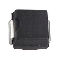
B1100-13-F Diodes Zetex, B1100-13-F Datasheet - Page 2

B1100-13-F
Manufacturer Part Number
B1100-13-F
Description
SCHOTTKY DIODE
Manufacturer
Diodes Zetex
Datasheet
1.B1100-13-F.pdf
(4 pages)
Specifications of B1100-13-F
Rectifier Type
Schottky Diode
Configuration
Single
Peak Rep Rev Volt
100V
Avg. Forward Curr (max)
1A
Rev Curr
500uA
Peak Non-repetitive Surge Current (max)
30A
Forward Voltage
0.79V
Operating Temp Range
-65C to 150C
Package Type
SMA
Operating Temperature Classification
Military
Mounting
Surface Mount
Pin Count
2
Lead Free Status / Rohs Status
Compliant
Available stocks
Company
Part Number
Manufacturer
Quantity
Price
Company:
Part Number:
B1100-13-F
Manufacturer:
Diodes Inc
Quantity:
187 572
Company:
Part Number:
B1100-13-F
Manufacturer:
DIODES
Quantity:
276
Part Number:
B1100-13-F
Manufacturer:
DIODES/美台
Quantity:
20 000
Single phase, half wave, 60Hz, resistive or inductive load.
For capacitance load, derate current by 20%.
Thermal Characteristics
Electrical Characteristics
Maximum Ratings
Peak Repetitive Reverse Voltage
Working Peak Reverse Voltage
DC Blocking Voltage
RMS Reverse Voltage
Average Rectified Output Current
Non-Repetitive Peak Forward Surge Current 8.3ms
Single Half Sine-Wave Superimposed on Rated Load
Repetitive Peak Reverse Current
Typical Thermal Resistance Junction to Terminal (Note 4)
Operating and Storage Temperature Range
Forward Voltage Drop
Leakage Current (Note 5)
Total Capacitance
Notes:
B170/B - B1100/B
Document number: DS30018 Rev. 10 - 2
0.01
1.0
4. Valid provided that terminals are kept at ambient temperature.
5. Short duration pulse test used to minimize self-heating effect.
0.1
10
0
V , INSTANTANEOUS FORWARD VOLTAGE (V)
F
Fig. 1 Typical Forward Characteristics
0.2
Characteristic
Characteristic
Characteristic
@T
0.4
A
= 25°C unless otherwise specified
@T
0.6
T = 25°C
I Pulse Width = 300µs
A
F
J
= 25°C unless otherwise specified
@ T
T
0.8
= 125°C
1.0
www.diodes.com
Symbol
Symbol
T
V
Symbol
V
V
J,
R(RMS)
I
R
I
2 of 4
RRM
RWM
V
FSM
RRM
I
T
θ JT
O
V
C
I
R
STG
R
F
T
1,000
B170/B
B170/B
100
Min
10
70
49
-
-
-
-
0.1
Fig. 2 Total Capacitance vs. Reverse Voltage
Typ
-
-
-
-
V , DC REVERSE VOLTAGE (V)
B180/B
B180/B
R
80
56
-65 to +150
Max
0.79
0.69
1
0.5
5.0
80
1.0
1.0
30
25
B190/B
B190/B
Unit
mA
pF
V
90
63
B170/B - B1100/B
10
I
I
@ Rated V
@ Rated V
V
F
F
R
= 1.0A, T
= 1.0A, T
= 4V, f = 1MHz
Test Condition
B1100/B
B1100/B
100
70
© Diodes Incorporated
September 2010
R
R
A
A
, T
, T
= 25°C
= 100°C
100
A
A
= 25°C
= 100°C
°C/W
Unit
Unit
°C
V
V
A
A
A


