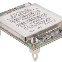
WLNG-SE-DP551 Quatech, WLNG-SE-DP551 Datasheet - Page 20

WLNG-SE-DP551
Manufacturer Part Number
WLNG-SE-DP551
Description
WiFi / 802.11 Modules & Development Tools WIRELESS DEV SERVER RS-422/485 SUPPORT
Manufacturer
Quatech
Series
Airborne™r
Specifications of WLNG-SE-DP551
Wireless Frequency
2.48 GHz
Interface Type
UART
Modulation
DBPSK, DQPSK, CCK, BPSK, QPSK, 16QAM, 64QAM
Security
64/128 bit WEP, WPA, AES, EAP
Antenna
U.FL
Operating Temperature Range
- 40 C to + 85 C
Mfg Application Notes
Transition to DP550 Devices AppNote
Frequency
2.4GHz ~ 2.4835GHz
Data Rate - Maximum
54Mbps
Modulation Or Protocol
802.11 b/g
Applications
WLAN
Power - Output
-
Sensitivity
-98dBm
Voltage - Supply
3.3VDC
Current - Receiving
310mA
Current - Transmitting
240mA
Data Interface
Connector, 36 Pin Header
Memory Size
-
Antenna Connector
U.FL x 2
Operating Temperature
-40°C ~ 85°C
Package / Case
Module
Lead Free Status / Rohs Status
Details
For Use With/related Products
ARM 9, AR6002
Quatech, Inc.
7.0
20
SPI Interface
The following section details the SPI interface specification for both hardware timing and
SPI protocol. The device is a SPI slave and requires a compatible SPI master for
operation.
7.1
Pin-out
When the SPI interface is enabled, through the CLI or web interface, the
following pins are assigned for communication.
Master In Slave Out (MISO)
Master Out Slave In (MOSI)
SPI Interrupt (SPI_INT)
SPI Clock (SPI_CLK)
SPI Select (/SPI_SEL)
Data In (RxD2, DTXD)
Data out (TxD2, DRXD)
Ready-to-Send (RTS2)
Clear-to-Send (CTS2)
Master In Slave Out (MISO)
Master Out Slave In (MOSI)
SPI Interrupt (SPI_INT)
SPI Clock (SPI_CLK)
SPI Select (/SPI_SEL)
Pin Definition
Pin Definition
Use of the SPI interface is mutually exclusive with the use of UART1 and the
Ethernet ports, as the API interface reuses pins from both of these interfaces.
Table 11 - SPI Signal Descriptions
Table 10 - SPI Pinout Details
4/14/2011
Serial Data OUT; must be connected to the serial data in of
the master.
Serial Data IN; Must be connected to the serial data out of the
master.
Interrupt signal driver by slave see Table 16 for details of
operation.
SPI clock sourced from the master.
Enable the SPI slave, sourced from the master. Active low
signal.
SPI
28
24
22
18
12
Description
UART2 Pin
21
17
19
9
Debug
100-8090-100
8
6


