MRF157 M/A-COM Technology, MRF157 Datasheet - Page 7
MRF157
Manufacturer Part Number
MRF157
Description
RF MOSFET Power 5-80MHz 600Watts 50Volt Gain 21dB
Manufacturer
M/A-COM Technology
Datasheet
1.MRF157.pdf
(9 pages)
Specifications of MRF157
Configuration
Single
Drain-source Breakdown Voltage
125 V
Gate-source Breakdown Voltage
40 V
Continuous Drain Current
60 A
Power Dissipation
1350 W
Maximum Operating Temperature
+ 150 C
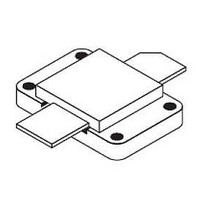
Package / Case
Case 368-03
Minimum Operating Temperature
- 65 C
Transistor Polarity
N-Channel
Lead Free Status / Rohs Status
Details
Available stocks
Company
Part Number
Manufacturer
Quantity
Price
Company:

Part Number:
MRF157
Manufacturer:
M/A-COM
Quantity:
5 000
Part Number:
MRF157
Manufacturer:
M/A-COM
Quantity:
20 000
Company:
Part Number:
MRF1570FNT1
Manufacturer:
GIGALANE
Quantity:
310
Part Number:
MRF1570FNT1
Manufacturer:
FREESCALE
Quantity:
20 000
Company:
Part Number:
MRF1570NT1
Manufacturer:
UMS
Quantity:
1 400
Part Number:
MRF1570NT1
Manufacturer:
FREESCALE
Quantity:
20 000
Part Number:
MRF157MP
Manufacturer:
M/A-COM
Quantity:
20 000


7
ADVANCED: Data Sheets contain information regarding a product M/A-COM Technology Solutions
is considering for development. Performance is based on target specifications, simulated results,
and/or prototype measurements. Commitment to develop is not guaranteed.
PRELIMINARY: Data Sheets contain information regarding a product M/A-COM Technology
Solutions has under development. Performance is based on engineering tests. Specifications are
typical. Mechanical outline has been fixed. Engineering samples and/or test data may be available.
Commitment to produce in volume is not guaranteed.
Linear RF Power MOSFET
600W, to 80MHz
MRF157
MOSFET CAPACITANCES
between the terminals. The metal oxide gate structure de-
termines the capacitors from gate–to–drain (Cgd), and
gate–to–source (Cgs). The PN junction formed during the
fabrication of the RF MOSFET results in a junction capaci-
tance from drain–to–source (Cds).
output (Coss) and reverse transfer (Crss) capacitances on
data sheets. The relationships between the inter–terminal
capacitances and those given on data sheets are shown
below. The
Ciss can be specified in two ways:
LINEARITY AND GAIN CHARACTERISTICS
sented, Figure 5 may give the designer additional informa-
tion on the capabilities of this device. The graph represents
the small signal unity current gain frequency at a given
drain current level. This is equivalent to fT for bipolar tran-
sistors. Since this test is performed at a fast sweep speed,
heating of the device does not occur. Thus, in normal use,
the higher temperatures may degrade these characteristics
to some extent.
DRAIN CHARACTERISTICS
full–on condition. This on–resistance, VDS(on), occurs in
the linear region of the output characteristic and is specified
under specific test conditions for gate–source voltage and
drain current. For MOSFETs, VDS(on) has a positive tem-
perature coefficient and constitutes an important design
consideration at high temperatures, because it contributes
to the power dissipation within the device.
The physical structure of a MOSFET results in capacitors
These capacitances are characterized as input (Ciss),
1.
2.
In addition to the typical IMD and power gain data pre-
One figure of merit for a FET is its static resistance in the
Drain shorted to source and positive voltage at the
gate.
Positive voltage of the drain in respect to source and
zero volts at the gate. In the latter case the numbers
are lower. However, neither method represents the
actual operating conditions in RF applications.
RF POWER MOSFET CONSIDERATIONS
GATE CHARACTERISTICS
is electrically isolated from the source by a layer of oxide.
The input resistance is very high — on the order of 109
ohms
— resulting in a leakage current of a few nanoamperes.
Gate control is achieved by applying a positive voltage
slightly in excess of the gate–to–source threshold voltage,
VGS(th).
rating. Exceeding the rated VGS can result in permanent
damage to the oxide layer in the gate region.
sentially capacitors. Circuits that leave the gate open–
circuited or floating should be avoided. These conditions
can result in turn–on of the devices due to voltage build–up
on the input capacitor due to leakage currents or pickup.
monolithic zener diode from gate–to–source. If gate protec-
tion is required, an external zener diode is recommended.
IMPEDANCE CHARACTERISTICS
tained by measuring their conjugates in an optimized nar-
row band test circuit. These test circuits are designed and
constructed for a number of frequency points depending on
the frequency coverage of characterization. For low fre-
quencies the circuits consist of standard LC matching net-
works including variable capacitors for peak tuning. At in-
creasing power levels the output impedance decreases,
resulting in higher RF currents in the matching network.
This makes the practicality of output impedance measure-
ments in the manner described questionable at power lev-
els higher than 200–300 W for devices operated at 50 V
and 150–200 W for devices operated at 28 V. The physical
sizes and values required for the components to withstand
the RF currents increase to a point where physical con-
struction of the output matching network gets difficult if not
impossible. For this reason the output impedances are not
given for high power devices such as the MRF154 and
MRF157.
d e s i g n
used to obtain reasonably close approximations to actual
values.
The gate of the RF MOSFET is a polysilicon material, and
Gate Voltage Rating — Never exceed the gate voltage
Gate Termination — The gates of these devices are es-
Gate Protection — These devices do not have an internal
Device input and output impedances are normally ob-
However, formulas like
M/A-COM Technology Solutions Inc. and its affiliates reserve the right to make
changes to the product(s) or information contained herein without notice.
• North America Tel: 800.366.2266 / Fax: 978.366.2266
• Europe Tel: 44.1908.574.200 / Fax: 44.1908.574.300
• Asia/Pacific Tel: 81.44.844.8296 / Fax: 81.44.844.8298
Visit www.macomtech.com for additional data sheets and product information.
or for a push–pull design can be
M/A-COM Products
Released - Rev. 07.07
for a single ended
Related parts for MRF157
Image
Part Number
Description
Manufacturer
Datasheet
Request
R
