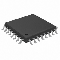
MAX3814CHJ+ Maxim Integrated Products, MAX3814CHJ+ Datasheet - Page 11

MAX3814CHJ+
Manufacturer Part Number
MAX3814CHJ+
Description
IC DRVR/EQUALIZER CABLE 32-TQFP
Manufacturer
Maxim Integrated Products
Type
Driverr
Datasheet
1.MAX3814CHJT.pdf
(14 pages)
Specifications of MAX3814CHJ+
Number Of Drivers/receivers
4/0
Voltage - Supply
3 V ~ 3.6 V
Mounting Type
Surface Mount
Package / Case
32-TQFP, 32-VQFP
Lead Free Status / RoHS Status
Lead free / RoHS Compliant
Protocol
-
Lead Free Status / Rohs Status
Lead free / RoHS Compliant
The MAX3814 is useful in providing equalization for
cables losses at location ZZ, at the input DVI/HDMI
connector of the remote display. It can equalize cable
lengths of 15 meters of 26 AWG wire and 12 meters of
28 AWG wire. Again, the 200Ω resistor placed at the
output of the MAX3814 absorbs reflections from the
imperfect termination of the ASIC or imperfect transmis-
sion-line interconnect.
The TMDS CML inputs are the most critical paths for
the MAX3814 and great care should be taken to mini-
mize discontinuities on these transmission lines
between the connector and the IC. Here are some sug-
gestions for maximizing the performance of the
MAX3814.
• The data and clock inputs should be wired direct-
ly between the cable connector and IC without
stubs.
GRAPHICS
BOARD
ASIC
MXM
CONNECTOR
ROUTING
SWITCH
LAPTOP
CMOS
______________________________________________________________________________________
Layout Considerations
MAX3814
Cable TMDS Equalizer
50Ω
3.3V
50Ω
3.3V
CONNECTOR
DOCKING
200Ω
MAX3814
DOCK
50Ω
3.3V
50Ω
3.3V
DVI/HDMI TMDS FR-4 and
200Ω
Cable Equalizer/Driver
• The 4-channel implementation treats all channels
• An uninterrupted ground plane should be posi-
• Ground-path vias should be placed close to the
• Maintain a 100Ω differential transmission line
• To minimize possible reflections, choose the
• Use good high-frequency layout techniques and
DVI/HDMI
CONNECTOR
identically. Input and output data channel designa-
tions are only a guide. Polarity assignments can be
swapped and channel paths can be interchanged.
tioned beneath the high-speed I/Os.
IC and the input/output interfaces to allow a return
current path to the IC and the DVI and HDMI
inputs.
impedance into and out of the MAX3814.
200Ω back termination option. Place this resistor
as close to the MAX3814 as possible.
multilayer boards with an uninterrupted ground
plane to minimize EMI and crosstalk. Refer to the
schematic and board layers of the MAX3814EVKIT.
EXTERNAL DVI/HDMI
Typical Application Circuits
CABLE
CONNECTOR
DVI/HDMI
MAX3814
50Ω
3.3V
50Ω
3.3V
REMOTE DISPLAY
200Ω
50Ω
3.3V
50Ω
3.3V
ASIC
11


