9-520272-2 TE Connectivity, 9-520272-2 Datasheet - Page 4
9-520272-2
Manufacturer Part Number
9-520272-2
Description
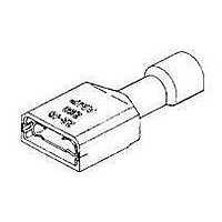
Terminals 110 ULTRA-FAST RCPT 22-18 TPBR
Manufacturer
TE Connectivity
Specifications of 9-520272-2
Product
Fastons
Wire Size (awg)
22-18
Insulation
Insulated
Color
Black
Gender
Female
Contact Plating
Tin
Contact Material
Brass
Termination Style
Crimp
Insulation Material
Nylon
Mounting Angle
Straight
Mounting Method
Wire
Number Of Positions / Contacts
1
Number Of Rows
1
Terminal Type
Receptacle
Proprietary Name
Ultra-Fast
Receptacle Style
Straight
Mating Area Interface Dimensions (mm [in])
2.79 x 0.81 [.110 x .032], 3.18 x 0.81 [.125 x .032]
Insulation Diameter (mm [in])
3.05 [.120] Max.
Insulation Support
Non-Insulation Support
Finish
Tin
Wire Range (mm [awg])
0.30-0.90² [22-18]
Fully Insulated
Yes
Ul Flammability Rating
UL 94V-2
Rohs/elv Compliance
RoHS compliant, ELV compliant
Lead Free Solder Processes
Not relevant for lead free process
Rohs/elv Compliance History
Always was RoHS compliant
Packaging Method
Strip
Lead Free Status / Rohs Status
Details
Available stocks
Company
Part Number
Manufacturer
Quantity
Price
Company:

Part Number:
9-520272-2
Manufacturer:
TE
Quantity:
20 000


3.6.
Rev D
Exam ination of Product
Dielectric W ithstanding Voltage,
Test Condition A
Dielectric W ithstanding Voltage,
Test Condition C
Dielectric W ithstanding Voltage,
Receptacle, Tab Entry Position
Heating (Tem perature Rise)
Heat Cycling (Current Cycling)
Pull Out (Crim p Tensile)
Secureness of Insulation
(Unassem bled)
Secureness of Insulation
(Assem bled)
Engagem ent-Disengagem ent
(Engaging-Separating)
Heat Age, 136 C
Heat Age/Hum idity
Term inal Tests and Sequences
NOTE
(Plain Brass)
.205/.187
Tab Size
Test or Exam ination
.250
.110
(a)
(b)
(c)
See paragraph 4.1.A.
Numbers indicate sequence in which tests are performed.
Uncrimped terminals and wires in test groups 4 and 11 shall be conditioned in the
environments indicated. After conditioning, each sample is crimped to the appropriate
wire and the electrical or mechanical test is performed.
Term inal
Plating
Tin
Engagem ent and Disengagem ent Forces
Individual
Insertion
(m ax)
First
17
15
12
1
1
2
3
Individual
2
1
2
3
(m ax)
17
20
14
Figure 2
Figure 3
3
1
3
2
3(c)
W ithdrawal
4
1
2
Average
(m in)
First
Force (pounds)
5
5
3
Test Sequence (b)
5
1
2
Test Group (a)
Individual
6
1
2
(m in)
3
3
2
1
7
2
1
8
2
Average
(m in)
4
3
2
W ithdrawal
1
9
3
2
Sixth
10
1
3
2
Individual
(m in)
3(c)
3
2
1
11
1
2
108-2043
12
1
2
4 of 5
Related parts for 9-520272-2
Image
Part Number
Description
Manufacturer
Datasheet
Request
R

Part Number:
Description:
CONN HEADR BRKWAY .100 52POS STR
Manufacturer:
Tyco Electronics
Datasheet:
Part Number:
Description:
CONN HEADR BRKWAY .100 52POS STR
Manufacturer:
Tyco Electronics
Part Number:
Description:
CONN HDR BRKWAY .100 52POS VERT
Manufacturer:
Tyco Electronics
Datasheet:
Part Number:
Description:
CONN HEADR BRKWAY .100 52POS R/A
Manufacturer:
Tyco Electronics
Datasheet:
Part Number:
Description:
CONN HEADR BRKWAY .100 52POS R/A
Manufacturer:
Tyco Electronics
Datasheet:
Part Number:
Description:
CONN HEADR BRKWAY .100 52POS R/A
Manufacturer:
Tyco Electronics
Datasheet:
Part Number:
Description:
CONN HDR BRKWAY .100 52POS VERT
Manufacturer:
Tyco Electronics
Datasheet:
Part Number:
Description:
CONN HEADR BRKWAY .100 52POS STR
Manufacturer:
Tyco Electronics
Datasheet:
Part Number:
Description:
CONN HEADR BRKWAY .100 52POS R/A
Manufacturer:
Tyco Electronics
Datasheet:
Part Number:
Description:
CONN HEADR BRKWAY .100 52POS R/A
Manufacturer:
Tyco Electronics
Datasheet:

Part Number:
Description:
Manufacturer:
TE Connectivity
Datasheet:

Part Number:
Description:
Manufacturer:
TE Connectivity
Datasheet:
Part Number:
Description:
187 PIDG FASTON REC
Manufacturer:
TE Connectivity
Datasheet:


Part Number:
Description:
RELAY, INDUSTRIAL, RT314012
Manufacturer:
TE Connectivity
Datasheet: