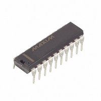
DS2186+ Maxim Integrated Products, DS2186+ Datasheet - Page 4

DS2186+
Manufacturer Part Number
DS2186+
Description
IC TRANSMIT LINE INTERFACE 20DIP
Manufacturer
Maxim Integrated Products
Type
Line Driver, Transmitterr
Datasheet
1.DS2186S.pdf
(11 pages)
Specifications of DS2186+
Number Of Drivers/receivers
1/0
Protocol
T1/CEPT
Voltage - Supply
4.75 V ~ 5.25 V
Mounting Type
Through Hole
Package / Case
20-DIP (0.300", 7.62mm)
Lead Free Status / RoHS Status
Lead free / RoHS Compliant
The shape of the “pre–emphasized” T1 waveform is
controlled by inputs LEN0, LEN1, and LEN2
(TCLKSEL=0). These control inputs allow the user to
select the appropriate output pulse shape to meet
DSX–1 or CSU templates over a wide variety of cable
types and lengths. Those cable types include ABAM,
PIC, and PULP.
The CEPT mode is enabled when TCLKSEL=1. Only
one output pulse shape is available in the CEPT mode;
inputs LEN0, LEN1 and LEN2 can be any state except
all zeros.
The line coupling transformer also contributes to the
pulse shape seen at the cross–connect point. Trans-
formers for both T1 and CEPT applications must be
1:1.35.
The wave shaping circuitry does not contribute signifi-
cantly to output jitter (less than 0.01 UIpp broadband).
Output jitter will be dominated by the jitter on TCLK or
LCLK. TCLK and LCLK need only be accurate in fre-
quency, not duty cycle.
T1 LINE LENGTH SELECTION Table 2
NOTE:
1. The LEN0, LEN1 and LEN2 inputs control T1 output waveshapes when TCLKSEL=0. The G.703 (CEPT) template
DS2186
022798 4/11
LEN2
is selected when TCLKSEL=1 and LEN0, LEN1, and LEN2 are at any state except all zeros.
0
0
0
0
1
1
1
1
LEN1
0
0
1
1
0
0
1
1
LEN0
0
1
0
1
0
1
0
1
OPTION SELECTED
Test mode
–7.5 dB buildout
–15 dB buildout
0 dB buildout,
0 – 133 feet
133 – 266 feet
266 – 399 feet
399 – 533 feet
533 – 655 feet
LINE DRIVERS
The on–chip differential line drivers interface directly to
the output transformer. To optimize device perform-
ance, length of the TTIP and TRING traces should be
minimized and isolated from neighboring interconnect.
FAULT PROTECTION
The line drivers are fault–protected and will withstand a
shorted transformer secondary (or primary) without
damage. Inputs MTIP and MRING are normally tied to
TTIP and TRING to provide fault monitoring capability.
Output LF will transition low if 192 TCLK cycles occur
without a one occurring at MTIP or MRING. LF will tri–
state on the next one occurrence or two TCLK periods
later, whichever is greater.
The threshold of MTIP and MRING varies with the line
type selected at LEN0, LEN1 and LEN2. This insures
detection of the lowest level zero to one transition (–15
dB buildout) as it occurs on TTIP and TRING.
APPLICATION
Do not use
T1 CSU
T1 CSU
T1 CSU, DSX–1 Cross connect
DSX–1 Cross connect
DSX–1 Cross connect
DSX–1 Cross connect
DSX–1 Cross connect


