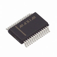
MAX3131EAI+ Maxim Integrated Products, MAX3131EAI+ Datasheet - Page 13

MAX3131EAI+
Manufacturer Part Number
MAX3131EAI+
Description
IC TXRX W/RS232 28-SSOP
Manufacturer
Maxim Integrated Products
Type
Transceiverr
Datasheet
1.MAX3130CAI.pdf
(16 pages)
Specifications of MAX3131EAI+
Number Of Drivers/receivers
2/2
Protocol
RS232
Voltage - Supply
3 V ~ 5 V
Mounting Type
Surface Mount
Package / Case
28-SSOP
Lead Free Status / RoHS Status
Lead free / RoHS Compliant
Power dissipation of the MAX3130/MAX3131, IR LED,
and R
duty cycle.
Use the following equations to calculate the power dis-
sipation in each component:
For reliable operation, do not exceed maximum power
dissipation of the components.
PIN photodiode selection is extremely important to sys-
tem performance. The PIN diode must generate at least
200nA (minimum sensitivity of the MAX3130/MAX3131)
of current when aimed ±15° off-axis with an incident
irradiance of 4µW/cm
mines if the Temic BPV22NF meets these requirements:
I
The first term (4mW/cm
irradiance in the ±15° angular range. The second term
(0.075cm
first 0.95 factor normalizes the sensitivity to the 875nm
wavelength and the second 0.95 factor adjusts for the
decreased receiver efficiency at ±15° off-axis. The 1.8
factor accounts for the round lens which increases the
effective PIN diode area. The last term (0.6A/W) is the
sensitivity of the PIN diode. Based on this example, the
Temic BPV22NF is an appropriate selection.
The final important factor in selecting a PIN diode is the
effective diode capacitance. It is important to keep this
capacitance below 70pF at 1.2V reverse bias. Higher
input capacitance compromises the noise performance
of the system by increasing the noise gain of the input
transimpedance amplifier.
The capacitor type used for C1–C4 is not critical for
proper operation; either polarized or nonpolarized
capacitors are good choices. The charge pump
requires 0.1µF capacitors for 3.3V operation. For other
supply voltages, refer to Table 2 for suggested capaci-
tor values. Do not use values smaller than those listed
in Table 2. Increasing the capacitor values (e.g., by a
factor of 2) reduces ripple on the transmitter outputs
and slightly reduces power consumption. C2, C3, and
C4 can be increased without changing C1’s value.
However, do not increase C1 without also increas-
ing the values of C2, C3, and C4.
PIN
MAX3130 power dissipation = I
IR LED power dissipation = I
R
SET
= 292nA
= (4µW/cm
SET
power dissipation = I
2
are based on the maximum LED current and
) is the sensitive area of the PIN diode. The
2
3V to 5.5V, IrDA Infrared Transceiver with
) (0.075cm
______________________________________________________________________________________
2
PIN Photodiode Selection
. The following equation deter-
2
) is the minimum guaranteed
2
) (0.95) (0.95) (1.8) (0.6A/W)
SET 2
Capacitor Selection
SET
SET
· R
· V
· V
SET
IRLED
DRV
· duty cycle
· duty cycle
· duty cycle
Integrated RS-232 Interface
When using the minimum required capacitor values,
make sure the capacitor value does not degrade
excessively with temperature. If in doubt, use capaci-
tors with a larger nominal value. The capacitor’s equiv-
alent series resistance (ESR) usually rises at low
temperatures and increases the amount of ripple on V+
and V-.
Because of the extremely sensitive nature of photodi-
ode amplifiers, it is important to maintain a low-noise
supply voltage. Use a separate analog supply voltage
where possible. Place a 1µF ceramic bypass capacitor
as close as possible to the AV
especially noisy systems, connect a small (10Ω) resis-
tor in series with V
capacitors.
Figure 4 shows how the MAX3130 is used to multiplex
between RS-232 and IrDA communication while using
only one UART. By using the IRMODE input, the type of
communication (infrared or RS-232) is controlled by the
I/O of a µP. The internal MAX3130 ENDEC is used to
translate between UART-type and IrDA-type bit-
streams. If the UART has this capability, connect
BAUD16 of the MAX3130 to GND.
Figure 5 shows the MAX3131 used with two UARTs to
perform simultaneous IrDA and RS-232 communication.
UART1 is a software UART used to perform infrared
IrDA communication. The internal ENDEC on the
MAX3131 translates between UART-type and IrDA-type
bit-streams. The MAX3100 is implemented as UART2
and communicates via the RS-232 interface. The
MAX3100 interfaces to the µP using a SPI interface.
The MAX3130/MAX3131 require careful layout tech-
niques to minimize parasitic signals coupling to the
PINC input. Keep the lead length between the photodi-
ode and PINC as short as possible. Keep PC board
traces to the PIN diode away from other noisy traces.
To minimize coupling, run the AGND trace adjacent to
the PINC trace on both sides. To prevent oscillation,
avoid routing the RXD trace near the PINC trace.
Connect the anode of the PIN diode, GND, and the
ground lead of the AV
connection. Keep the output pins RXD and TXD as
short as possible to minimize coupling back to the input
via parasitic capacitance.
IrDA or RS-232 Application Circuit
Power-Supply Noise Rejection
CC
, in addition to the normal bypass
CC
Layout Considerations
bypass capacitor in a star-
CC
and V
CC
pins. In
13


