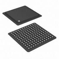
DS21448 Maxim Integrated Products, DS21448 Datasheet - Page 32

DS21448
Manufacturer Part Number
DS21448
Description
IC LIU QUAD E1/T1/J1 144-BGA
Manufacturer
Maxim Integrated Products
Type
Line Interface Units (LIUs)r
Datasheet
1.DS21448L.pdf
(60 pages)
Specifications of DS21448
Number Of Drivers/receivers
4/4
Protocol
T1/E1/J1
Voltage - Supply
3.135 V ~ 3.465 V
Mounting Type
Surface Mount
Package / Case
144-BGA
Lead Free Status / RoHS Status
Contains lead / RoHS non-compliant
Available stocks
Company
Part Number
Manufacturer
Quantity
Price
Company:
Part Number:
DS21448
Manufacturer:
DALLAS
Quantity:
140
Company:
Part Number:
DS21448+
Manufacturer:
MAXIM
Quantity:
2 622
Company:
Part Number:
DS21448LN+
Manufacturer:
ROHM
Quantity:
12 000
Part Number:
DS21448LN+
Manufacturer:
MAXIM/美信
Quantity:
20 000
Table 6-C. Definition of Received Errors
Table 6-D. Function of ECRS Bits and RNEG Pin
Note 1: RNEG outputs error data only when in NRZ mode (CCR1.6 = 1).
Note 2: PRBS errors are always output at PBEO, independent of ECR control bits and NRZ mode, and are not present at RNEG.
6.5 Error Counter Update
A 0-to-1 transition of the ECUE (CCR1.4) control bit updates the ECR registers with the current values and resets
the counters. ECUE must be set back to 0 and another 0-to-1 transition must occur for subsequent reads/resets of
the ECR registers. Note that the DS21448 can report errors at RNEG when in NRZ mode (CCR1.6 = 1) by
outputting a pulse for each error occurrence. The counter saturates at 65,535 and does not roll over.
ECR1 (11H): Upper Error Count Register 1/ECR2 (12H): Lower Error Count Register 2
6.6 Error Insertion
When IBPV (CCR3.1) is transitioned from 0 to 1, the device waits for the next occurrence of three consecutive 1s
to insert a BPV. IBPV must be cleared and set again for another BPV error insertion. See
the insertion of the BPV into the data stream.
When IBE (CCR3.0) is transitioned from 0 to 1, the device inserts a logic error. IBE must be cleared and set again
for another logic error insertion. See
data steam.
ERROR
(CCR1.7)
(MSB)
PRBS
NAME
E1 or T1
BPV
EXZ
EXZ
E15
E15
CV
E7
E0
X
0
0
0
0
1
1
1
1
E1 OR T1
E1/T1
E1/T1
POSITION
E1
E1
T1
ECR1.7
ECR2.0
(CCR6.2)
E14
E6
ECRS2
0
0
0
0
0
0
0
0
1
Two consecutive marks with the same polarity. Ignores BPVs because of HDB3 and B8ZS zero
suppression when CCR2.3 = 0. Typically used with AMI coding (CCR2.3 = 1). ITU-T O.161.
When HDB3 is enabled (CCR2.3 = 0) and the receiver detects two consecutive BPVs with the same
polarity. ITU-T O.161.
When four or more consecutive zeros are detected.
When receiving AMI-coded signals (CCR2.3 = 1), detection of 16 or more 0s or a BPV. ANSI T1.403
1999.
When receiving B8ZS-coded signals (CCR2.3 = 0), detection of eight or more 0s or a BPV. ANSI
T1.403 1999.
A bit error in a received PRBS pattern. See Section
MSB of the 16-bit error count.
LSB of the 16-bit error count.
E13
E5
(CCR6.1)
ECRS1
X
X
X
X
X
0
0
1
1
Figure 1-2
E12
E4
(CCR6.0)
ECRS0
X
0
1
0
1
0
1
0
1
and
DEFINITION OF RECEIVED ERRORS
32 of 60
Figure 1-3
E11
E3
(CCR2.3)
RHBE
X
X
X
X
X
0
0
1
1
for details about the logic error insertion into the
FUNCTION
E10
E2
6.3
FUNCTION OF ECR COUNTERS/RNEG
for details. ITU-T O.151.
BPVs (HDB3 codewords not counted)
BPVs (B8ZS codewords not counted)
E9
E1
PRBS Errors (Note 2)
BPVs + 16 EXZs
BPVs + 8 EXZs
BPVs + EXZs
CVs + EXZs
(Note 1)
BPVs
CVs
Figure 1-3
(LSB)
E8
E0
for details on
ECR1
ECR2


