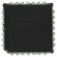
CY7B9234-270JXC Cypress Semiconductor Corp, CY7B9234-270JXC Datasheet - Page 9

CY7B9234-270JXC
Manufacturer Part Number
CY7B9234-270JXC
Description
IC TRANSMITTER HOTLINK 28-PLCC
Manufacturer
Cypress Semiconductor Corp
Series
HOTlink™r
Type
Transmitter and Receiverr
Datasheet
1.CY7B9234-270JXC.pdf
(36 pages)
Specifications of CY7B9234-270JXC
Package / Case
28-PLCC
Protocol
Fibre Channel
Voltage - Supply
4.5 V ~ 5.5 V
Mounting Type
Surface Mount
Product
PHY
Supply Voltage (min)
4.5 V
Supply Current
0.085 A
Maximum Operating Temperature
+ 70 C
Minimum Operating Temperature
0 C
Mounting Style
SMD/SMT
Number Of Channels
1
Lead Free Status / RoHS Status
Lead free / RoHS Compliant
Number Of Drivers/receivers
-
Lead Free Status / RoHS Status
Lead free / RoHS Compliant, Lead free / RoHS Compliant
Other names
428-2905-5
CY7B9234-270JXC
CY7B9234-270JXC
Available stocks
Company
Part Number
Manufacturer
Quantity
Price
Company:
Part Number:
CY7B9234-270JXC
Manufacturer:
CY
Quantity:
10
Company:
Part Number:
CY7B9234-270JXC
Manufacturer:
CYPRESS
Quantity:
831
Company:
Part Number:
CY7B9234-270JXC
Manufacturer:
Cypress Semiconductor Corp
Quantity:
10 000
Company:
Part Number:
CY7B9234-270JXCT
Manufacturer:
Cypress Semiconductor Corp
Quantity:
10 000
Maximum Ratings
Exceeding maximum ratings may impair the useful life of device.
These user guidelines are not tested.
Storage Temperature ......................................−65°C to +150°C
Ambient Temperature with
Power Applied..................................................−55°C to +125°C
Supply Voltage to Ground Potential ................ −0.5V to +7.0V
DC Input Voltage ................................................ −0.5V to +7.0V
Output Current into TTL Outputs (LOW) ..................... 30 mA
Output Current into PECL outputs (HIGH) .................. −50 mA
CY7B9234/CY7B9334 Electrical Characteristics
Document #: 38-02014 Rev. *B
V
V
I
V
V
I
I
V
V
V
V
V
I
I
Notes
Parameter
OST
IHT
ILT
IHE
ILE
1. See the last page of this specification for Group A subgroup testing information.
2. Tested one output at a time, output shorted for less than one second, less than 10% duty cycle.
3. Applies to A/B only.
4. Input currents are always positive at all voltages above V
5. Maximum I
6. Maximum I
TTL OUTs, CY7B9234: RP; CY7B9334: Q
TTL INs, CY7B9234: D
Transmitter PECL-Compatible Output Pins: OUTA+, OUTA−, OUTB+, OUTB−, OUTC+, OUTC−
Receiver PECL-Compatible Input Pins: A/B, SI, INB
OHT
OLT
IHT
ILT
OHE
OLE
ODIF
IHE
ILE
[3]
[3]
measured with V
(pin 9 and pin 22) only. Current into V
pair adds 5 mA to I
the output load current should be multiplied by 1V instead of V
= LOW, and outputs unloaded. I
current plus the sum of all the load currents for each output pin. The total buffer quiescent current is 10mA max., and max. TTL load current for each output pin can be
calculated as follows: Where R
included to account for worst process corner and temperature condition.
CCT
CCR
Output HIGH Voltage
Output LOW Voltage
Output Short Circuit Current
Input HIGH Voltage
Input LOW Voltage
Input HIGH Current
Input LOW Current
Output HIGH Voltage
(V
Output LOW Voltage
(V
Output Differential Voltage
|(OUT+) − (OUT−)|
Input HIGH Voltage
Input LOW Voltage
Input HIGH Current
Input LOW Current
is measured with V
CC
CC
is measured with V
CC
CCT
referenced)
referenced)
= 5.0V, T
and an additional load current to V
Description
0−7
A
L
=equivalent load resistance, C
= 25°C, one output pair loaded with 50 ohms to V
, SC/D, SVS, ENA, ENN, CKW, FOTO, BISTEN; CY7B9334: RF, REFCLK, BISTEN
CCR
CC
CC
includes current into V
CCN
= Max., one PECL output pair loaded with 50 ohms to V
= Max., RF = LOW, and outputs unloaded. Typical I
is determined by PECL load currents, typically 30 mA with 50 ohms to V
TTLPin
I I CCN
+
0−7
0.95) (V CCN * 5)*0.3
, SC/D, RVS, RDY, CKR, SO
CCN
I
I
V
V
V
Load = 50Ω to
V
Load = 50Ω to
V
Load = 50 ohms to V
V
V
CC
CCQ
OH
OL
CC
CC
OUT
IN
IN
IN
IN
/2.
L
as described. When calculating the contribution of PECL load currents to chip power dissipation,
=capacitive load, and F
= 4 mA
= V
= 0.0V
= V
= V
= − 2 mA
(pins 21 and 24). Current into V
CC
R L
− 2V
− 2V
=0V
.
CC
IHE
ILE
[2]
Min.
Max.
Test Conditions
) C L *
Com’l, Ind’l, & Mil
Ind’l & Mil
Com’l
Ind’l & Mil
Com’l
Ind’l & Mil
Com’l
Ind’l & Mil
Com’l
Ind’l & Mil
CC
Static Discharge Voltage........................................... > 4001V
(per MIL−STD−883, Method 3015)
Latch-Up Current .................................................... > 200 mA
Operating Range
Over the Operating Range
− 2.0V, others tied to V
Commercial
Industrial
Military
V CCN
CC
pin
2
Range
=frequency in MHz of data on pin. A derating factor of 1.1 has been
− 2V
) 1.5 * F pin * 1.1
(CKW and FOTO, only)
CCR
CCN
CC
is measured with V
(pin 9) is determined by the total TTL output buffer quiescent
− 2.0V, and other PECL outputs tied to V
−55
°
CC
C to +125
, BISTEN = LOW. I
Ambient Temperature
−40
CC
[1]
0
CC
V
V
V
V
V
V
°
CC
= 5.0V, T
C to +70
CC
CC
CC
CC
CC
°
− 2.0V. Each additional enabled PECL
°
−0.5
+0.5
C to +85
Min
−10
−15
2.4
2.0
2.2
0.6
2.0
2.0
C Case Temperature 5V ± 10%
−1.165
−1.03
−1.05
−1.86
−1.96
−1.14
A
CCT
= 25°C, RF = LOW, BISTEN
°
C
°
includes current into V
C
V
V
V
V
V
V
CC
CC
CC
CC
CC
CC
− 500
+500
Max
0.45
−90
V
V
+10
V
V
0.8
CC
−1.475
−0.83
−0.83
−1.62
−1.62
−1.50
CC
CC
CC
CC
. Typical I
CY7B9234
CY7B9334
Page 9 of 36
5V ± 10%
5V ± 10%
CCT
Unit
V
mA
μA
μA
μA
μA
CCQ
V
V
V
V
V
V
V
V
V
V
V
V
V
V
CC
is
[+] Feedback


