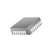
CY7B9334-270JXCT Cypress Semiconductor Corp, CY7B9334-270JXCT Datasheet - Page 8

CY7B9334-270JXCT
Manufacturer Part Number
CY7B9334-270JXCT
Description
IC RECEIVER HOTLINK 28-PLCC
Manufacturer
Cypress Semiconductor Corp
Series
HOTlink™r
Type
Transmitter and Receiverr
Datasheet
1.CY7B9234-270JXC.pdf
(36 pages)
Specifications of CY7B9334-270JXCT
Package / Case
28-PLCC
Protocol
Fibre Channel
Voltage - Supply
4.5V ~ 5.5V
Mounting Type
Surface Mount
Product
PHY
Supply Voltage (min)
4.5 V
Supply Current
0.155 A
Maximum Operating Temperature
+ 70 C
Minimum Operating Temperature
0 C
Mounting Style
SMD/SMT
Number Of Channels
1
Lead Free Status / RoHS Status
Lead free / RoHS Compliant
Number Of Drivers/receivers
-
Lead Free Status / RoHS Status
Lead free / RoHS Compliant, Lead free / RoHS Compliant
Available stocks
Company
Part Number
Manufacturer
Quantity
Price
Company:
Part Number:
CY7B9334-270JXCT
Manufacturer:
Cypress Semiconductor Corp
Quantity:
10 000
Output Register
The Output register holds the recovered data (Q
RVS) and aligns it with the recovered byte clock (CKR). This synchro-
nization insures proper timing to match a FIFO interface or other logic
that requires glitch free and specified output behavior. Outputs
change synchronously with the rising edge of CKR.
In BIST mode, this register becomes the signature pattern
generator and checker by logically converting itself into a Linear
Feedback Shift Register (LFSR) pattern generator.
enabled, this LFSR will generate a 511-byte sequence that
includes all Data and Special Character codes, including the
explicit violation symbols.
but pseudo-random sequence that can be matched to an
identical LFSR in the Transmitter. When synchronized, it checks
each byte in the Decoder with each byte generated by the LFSR
and shows errors at RVS. Patterns generated by the LFSR are
compared after being buffered to the output pins and then fed
back to the comparators, allowing test of the entire receive
function.
Document #: 38-02014 Rev. *B
This pattern provides a predictable
0
−
7
, SC/D, and
When
In BIST mode, the LFSR is initialized by the first occurrence of
the transmitter BIST loop start code D0.0 (D0.0 is sent only once
per BIST loop). Once the BIST loop has been started, RVS will
be HIGH for pattern mismatches between the received sequence
and the internally generated sequence. Code rule violations or
running disparity errors that occur as part of the BIST loop will
not cause an error indication. RDY will pulse HIGH once per BIST
loop and can be used to check test pattern progress. The receiver
BIST generator can be reinitialized by leaving and re-entering BIST
mode.
Test Logic
Test logic includes the initialization and control for the Built-In
Self-Test (BIST) generator, the multiplexer for Test mode clock
distribution, and control logic for the decoder. Test logic is
discussed in more detail in the CY7B9334 SMPTE HOTLink
Receiver Operating Mode Description.
CY7B9234
CY7B9334
Page 8 of 36
[+] Feedback


