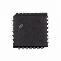
DP8392CV National Semiconductor, DP8392CV Datasheet - Page 3

DP8392CV
Manufacturer Part Number
DP8392CV
Description
IC TRANSCEIVER COAX INT 28-PLCC
Manufacturer
National Semiconductor
Series
DPr
Type
Transceiverr
Datasheet
1.DP8392CV.pdf
(12 pages)
Specifications of DP8392CV
Number Of Drivers/receivers
1/1
Protocol
IEEE 802
Voltage - Supply
9V
Mounting Type
Surface Mount
Package / Case
*
Lead Free Status / RoHS Status
Contains lead / RoHS non-compliant
Other names
*DP8392CV
Available stocks
Company
Part Number
Manufacturer
Quantity
Price
Company:
Part Number:
DP8392CV
Manufacturer:
NSC
Quantity:
1 995
Part Number:
DP8392CV
Manufacturer:
NS/国半
Quantity:
20 000
Company:
Part Number:
DP8392CV-1
Manufacturer:
NSC
Quantity:
1 584
Company:
Part Number:
DP8392CV-1
Manufacturer:
Texas Instruments
Quantity:
10 000
Part Number:
DP8392CV-1
Manufacturer:
NS/国半
Quantity:
20 000
Company:
Part Number:
DP8392CV-2
Manufacturer:
NSC
Quantity:
5 510
Company:
Part Number:
DP8392CV-2
Manufacturer:
CDC
Quantity:
5 510
Part Number:
DP8392CV-2
Manufacturer:
HARRIS
Quantity:
20 000
Part Number:
DP8392CVX
Manufacturer:
NS/国半
Quantity:
20 000
3 0 Functional Description
3 3 COLLISION FUNCTIONS
The collision circuitry consists of two buffers two 4-pole
Bessel low pass filters (section 3 1) a comparator a heart-
beat generator a 10 MHz oscillator and a differential line
driver
Two identical buffers and 4-pole Bessel low pass filters ex-
tract the DC level on the center conductor (data) and the
shield (sense) of the coax These levels are monitored by
the comparator If the data level is more negative than the
sense level by at least the collision threshold (Vth) the colli-
sion output is enabled
At the end of every transmission the heartbeat generator
creates a pseudo collision for a short time to ensure that the
collision circuitry is properly functioning This burst on colli-
sion output occurs typically 1 1
and has a duration of about 1 s This function can be dis-
abled externally with the HBE (Heartbeat Enable) pin to al-
low operation with repeaters
s after the transmission
(Continued)
FIGURE 3 Transmitter Timing
FIGURE 2 Receiver Timing
3
The 10 MHz oscillator generates the signal for the collision
and heartbeat functions It is also used as the timebase for
all the jabber functions It does not require any external
components
The collision differential line driver transfers the 10 MHz sig-
nal to the CD
heartbeat conditions This line driver also features zero dif-
ferential idle state
3 4 JABBER FUNCTIONS
The Jabber Timer monitors the Transmitter and inhibits
transmission if the Transmitter is active for longer than
20 ms (fault) It also enables the collision output for the fault
duration After the fault is removed The Jabber Timer waits
for about 500 ms (unjab time) before re-enabling the Trans-
mitter The transmit input must stay inactive during the unjab
time
g
pair in the event of collision jabber or
TL F 11085– 3
TL F 11085– 4


