DS275 Maxim Integrated Products, DS275 Datasheet
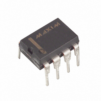
IC TXRX LINE-PWR RS232 8-DIP

DS275

Manufacturer Part Number
DS275
Description
IC TXRX LINE-PWR RS232 8-DIP
Manufacturer
Maxim Integrated Products
Type
Transceiverr
Datasheet

Specifications of DS275

Number Of Drivers/receivers
1/1
Protocol
RS232
Voltage - Supply
4.5 V ~ 5.5 V
Mounting Type
Through Hole
Package / Case
8-DIP (0.300", 7.62mm)
Lead Free Status / RoHS Status
Contains lead / RoHS non-compliant

Available stocks

Company
Part Number
Manufacturer
Quantity
Price
Part Number:
DS275
Manufacturer:
DALLAS
Quantity:
5 510
Part Number:
DS2751E
Manufacturer:
MAXIM
Quantity:
361
Part Number:
DS2751E
Manufacturer:
MAXIM/美信
Quantity:
20 000
Part Number:
DS2751E+TR
Manufacturer:
MAXIM/美信
Quantity:
20 000
Part Number:
DS2751E/T
Manufacturer:
MAXIM/美信
Quantity:
20 000
Part Number:
DS2751R
Manufacturer:
MAXIM/美信
Quantity:
20 000
Part Number:
DS2756E
Manufacturer:
MAXIM/美信
Quantity:
20 000
Part Number:
DS275E
Manufacturer:
SIPEX
Quantity:
6 851
FEATURES
ORDERING INFORMATION
DS275
DS275S
DS275E
DESCRIPTION
The DS275 Line-Powered RS-232 Transceiver Chip is a CMOS device that provides a low-cost, very
low-power interface to RS-232 serial ports. The receiver input translates RS-232 signal levels to common
CMOS/TTL levels. The transmitter employs a unique circuit which steals current from the receive RS-
232 signal when that signal is in a negative state (marking). Since most serial communication ports
remain in a negative state statically, using the receive signal for negative power greatly reduces the
DS275’s static power consumption. This feature is especially important for battery-powered systems such
as laptop computers, remote sensors, and portable medical instruments. During an actual communication
session, the DS275’s transmitter will use system power (5-12 volts) for positive transitions while still
employing the receive signal for negative transitions.
www.dalsemi.com
Low-power serial transmitter/receiver for
battery-backed systems
Transmitter steals power from receive signal
line to save power
Ultra-low static current, even when connected
to RS-232-E port
Variable transmitter level from +5 to +12
volts
Compatible with RS-232-E signals
Available in 8-pin, 150 mil wide SOIC
package (DS275S)
Low-power CMOS
8-pin DIP
8-pin SOIC
14-pin TSSOP
Line-Powered RS-232 Transceiver Chip
1 of 8
PIN ASSIGNMENT
PIN DESCRIPTION
RX
V
TX
GND
TX
NC
RX
V
DRV
CC
IN
OUT
OUT
IN
DS275 8-Pin SOIC (150-mil)
RX
DS275 8-Pin DIP (300-mil)
GND
RX
V
TX
GND
NC
NC
NC
OUT
DRV
V
TX
DS275E 14-Pin TSSOP
OUT
DRV
IN
IN
- RS-232 Receiver Output
- Transmit driver +V
- RS-232 Driver Input
- System Ground (0V)
- RS-232 Driver Output
- No Connection
- RS-232 Receive Input
-System Logic Supply (+5V)
1
2
3
4
5
6
7
1
2
3
4
8
7
6
5
14
13
12
11
10
9
8
V
RX
NC
TX
V
NC
NC
RX
NC
NC
TX
CC
OUT
CC
IN
OUT
IN
DS275
112299

Related parts for DS275

DS275 Summary of contents

Page 1

... DS275’s static power consumption. This feature is especially important for battery-powered systems such as laptop computers, remote sensors, and portable medical instruments. During an actual communication session, the DS275’s transmitter will use system power (5-12 volts) for positive transitions while still employing the receive signal for negative transitions. ...

Page 2

... Since most asynchronous communication over an RS-232 connection typically remains in a marking state when data is not being sent, the DS275 will not consume system power in this condition. System power would only be used when positive-going transitions are ...

Page 3

... RS-232 COMPATIBILITY The intent of the DS275 is not so much to meet all the requirements of the RS-232 specification as to offer a low-power solution that will work with most RS-232 ports with a connector length of less than 10 feet prime example, the DS275 will not meet the RS-232 requirement that the signal levels be at ...

Page 4

... NOTE: The capacitor stores negative charge whenever the TXD signal from the PC serial port marking data state (a negative voltage that is typically -10 volts). The top DS275’s TX charge reservoir when marking state. The capacitor will discharge to 0 volts when the TXD line ...

Page 5

... SYMBOL MIN TYP V 4.5 5 4.5 5-12 DRV 400 DRV1 I 40 CC1 I 3.8 DRV1 I 40 CC1 I 1.5 DRV2 I 10.0 CC2 I 3.8 DRV2 I 10.0 CC2 I 0.05 DRV3 DS275 MAX UNITS NOTES +0 800 100 A 3 5.0 A 100 A A 10.0 15 5.0 mA 20 ...

Page 6

... See test circuit in Figure 6. loaded ground and OUT -10 volts and see Figure 7. IN OUT HYS TH TL SYMBOL MIN TYP V 3.5 4.0 OTXH V -8.5 -9.0 OTXL I + 0.8 1 1.6 2 0.5 0.8 HYS I -1 loaded ground. OUT DS275 = 10 DRV MAX UNITS NOTES 5 + 1 3.2 mA ...

Page 7

... DYNAMIC OPERATING CURRENT TEST CIRCUIT Figure 4 STATIC OPERATING CURRENT TEST CIRCUIT Figure 5 DRIVER LEAKAGE TEST CIRCUIT Figure DS275 ...

Page 8

... PROPAGATION DELAY TEST CIRCUIT Figure 7 DS275E 14-PIN TSSOP DIM phi DS275 14-PIN MIN MAX - 1.10 0.05 - 0.75 1.05 0.18 0.30 0.09 0.18 4.90 5.10 4.40 NOM 0.65 BSC 0.25 REF 6.25 6.55 0.50 0. ...

Related keywords