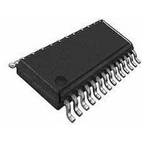
ST62T65CN6 STMicroelectronics, ST62T65CN6 Datasheet - Page 30

ST62T65CN6
Manufacturer Part Number
ST62T65CN6
Description
Microcontrollers (MCU) OTP EPROM 4K SPI
Manufacturer
STMicroelectronics
Datasheet
1.ST62T55CM6.pdf
(86 pages)
Specifications of ST62T65CN6
Processor Series
ST62T6x
Core
ST6
Data Bus Width
8 bit
Program Memory Type
EPROM
Program Memory Size
3884 B
Data Ram Size
128 B
Interface Type
SCI
Maximum Clock Frequency
8 MHz
Number Of Programmable I/os
21
Number Of Timers
1
Operating Supply Voltage
3 V to 6 V
Maximum Operating Temperature
+ 125 C
Mounting Style
SMD/SMT
Package / Case
SSOP-28
Minimum Operating Temperature
- 40 C
On-chip Adc
8 bit
Lead Free Status / Rohs Status
Details
Available stocks
Company
Part Number
Manufacturer
Quantity
Price
Company:
Part Number:
ST62T65CN6
Manufacturer:
SEK
Quantity:
1 000
Part Number:
ST62T65CN6
Manufacturer:
ST
Quantity:
20 000
ST62T55C ST62T65C/E65C
DIGITAL WATCHDOG (Cont’d)
These instructions test the C bit and Reset the
MCU (i.e. disable the Watchdog) if the bit is set
(i.e. if the Watchdog is active), thus disabling the
Watchdog.
In all modes, a minimum of 28 instructions are ex-
ecuted after activation, before the Watchdog can
generate a Reset. Consequently, user software
should load the watchdog counter within the first
27 instructions following Watchdog activation
(software mode), or within the first 27 instructions
executed following a Reset (hardware activation).
It should be noted that when the GEN bit is low (in-
terrupts disabled), the NMI interrupt is active but
cannot cause a wake up from STOP/WAIT modes.
Figure 19. Digital Watchdog Block Diagram
30/86
S
RSFF
RESET
Q
R
DB0
DB1.7
8
WRITE
DATA BUS
-2
LOAD
7
RESET
SET
Figure 18. A typical circuit making use of the
EXERNAL STOP MODE CONTROL feature
SWITCH
SET
-2
8
OSCILLATOR
CLOCK
-12
VA00010
NMI
I/O
VR02002


