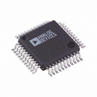
ADV7171KS Analog Devices Inc, ADV7171KS Datasheet - Page 31

ADV7171KS
Manufacturer Part Number
ADV7171KS
Description
IC DAC VIDEO ENC NTSC 44-MQFP
Manufacturer
Analog Devices Inc
Type
Video Encoderr
Datasheet
1.ADV7171KSUZ.pdf
(64 pages)
Specifications of ADV7171KS
Rohs Status
RoHS non-compliant
Applications
Set-Top Boxes, Video Players
Voltage - Supply, Analog
4.75 V ~ 5.25 V
Mounting Type
Surface Mount
Package / Case
44-MQFP, 44-PQFP
Adc/dac Resolution
10b
Screening Level
Industrial
Package Type
MQFP
Pin Count
44
Voltage - Supply, Digital
-
Lead Free Status / RoHS Status
Not Compliant
Available stocks
Company
Part Number
Manufacturer
Quantity
Price
Part Number:
ADV7171KS
Manufacturer:
ADI/亚德诺
Quantity:
20 000
Company:
Part Number:
ADV7171KSU
Manufacturer:
AD
Quantity:
319
Part Number:
ADV7171KSU
Manufacturer:
ADI/亚德诺
Quantity:
20 000
Company:
Part Number:
ADV7171KSUZ
Manufacturer:
LTC
Quantity:
20
Company:
Part Number:
ADV7171KSUZ
Manufacturer:
ADI
Quantity:
246
Company:
Part Number:
ADV7171KSUZ
Manufacturer:
Analog Devices Inc
Quantity:
10 000
Part Number:
ADV7171KSUZ
Manufacturer:
ADI/亚德诺
Quantity:
20 000
Company:
Part Number:
ADV7171KSUZ-REEL
Manufacturer:
Analog Devices Inc
Quantity:
10 000
Company:
Part Number:
ADV7171KSZ
Manufacturer:
Analog Devices Inc
Quantity:
10 000
Part Number:
ADV7171KSZ
Manufacturer:
ADI/亚德诺
Quantity:
20 000
Company:
Part Number:
ADV7171KSZ-REEL
Manufacturer:
Analog Devices Inc
Quantity:
10 000
Genlock Control (MR22 to MR21)
These bits control the genlock feature of the ADV7170/
ADV7171. Setting MR21 to a Logic Level 1 configures the
SCRESET/RTC pin as an input. Setting MR22 to Logic Level 0
configures the SCRESET/RTC pin as a subcarrier reset input.
Therefore, the subcarrier resets to Field 0 following a low-to-
high transition on the SCRESET/RTC pin. Setting MR22 to
Logic Level 1 configures the SCRESET/RTC pin as a real-time
control input.
Active Video Line Duration (MR23)
This bit switches between two active video line durations.
A 0 selects CCIR REC601 (720 pixels PAL/NTSC), and
MR37
INPUT DEFAULT
0
1
MR17
COLOR
COLOR BAR
0
1
DISABLE
ENABLE
CONTROL
RESERVED
MR37
MR27
MR27
DISABLE
ENABLE
MR36
MR17
0
1
MODE CONTROL
MR26
LOW POWER MODE
MR16
TTXRQ BIT
0
1
0
1
NORMAL
BIT REQUEST
MR36
CONTROL
NORMAL
POWER-DOWN
MR26
DISABLE
ENABLE
DAC A
MR16
MR25
MR35
0
1
0
1
MR15
TELETEXT
ENABLE
0
1
MR35
CONTROL
ENABLE BURST
DISABLE BURST
DISABLE
ENABLE
BURST
CONTROL
MR25
NORMAL
POWER-DOWN
DAC B
MR15
CHROMA OUTPUT
MR34
MR24
0
1
0
1
MR14
SELECT
CHROMINANCE
MR34
0
1
CONTROL
ENABLE COLOR
DISABLE COLOR
DISABLE
ENABLE
Figure 39. Mode Register 1
Figure 40. Mode Register 2
Figure 41. Mode Register 3
MR33
CONTROL
MR24
NORMAL
POWER-DOWN
0
1
MR14
Rev. C | Page 31 of 64
DAC D
MR23
COMPOSITE
GREEN/LUMA/Y
MR13
0
1
MR33
0
1
ACTIVE VIDEO LINE
DAC A
MR23
CONTROL
MR13
720 PIXELS
710 PIXELS/702 PIXELS
MR32
NORMAL
POWER-DOWN
DAC C
DURATION
0
1
VBI_OPEN
a 1 selects ITU-R.BT470 standard for active video duration
(710 pixels NTSC; 702 pixels PAL).
Chrominance Control (MR24)
This bit enables the color information to be switched on and off
the video output.
Burst Control (MR25)
This bit enables the burst information to be switched on and off the
video output.
Low Power Mode (MR26)
This bit enables the lower power mode of the ADV7170/
ADV7171, reducing the DAC current by 45%.
MR22 MR21
MR32
x
0
1
DISABLE
ENABLE
MR12 MR11
BLUE/COMP/U
BLUE/COMP/U
0
0
1
1
GENLOCK CONTROL
MR22
MR12
CLOSED CAPTIONING
0
1
1
DAC B
FIELD SELECTION
DAC OUTPUT
0
1
0
1
DISABLE GENLOCK
ENABLE SUBCARRIER
RESET PIN
ENABLE RTC PIN
MR31
NO DATA OUT
ODD FIELD ONLY
EVEN FIELD ONLY
DATA OUT
(BOTH FIELDS)
MR21
MR11
RED/CHROMA/V
RED/CHROMA/V
RESERVED
MR10
MR30
MR30
MR31
0
1
DAC C
MR20
SQUARE PIXEL
0
1
INTERLACE
INTERLACED
NONINTERLACED
MR10
MR20
CONTROL
CONTROL
DISABLE
ENABLE
GREEN/LUMA/Y
COMPOSITE
DAC D
ADV7170/ADV7171


