C2012C0G2A332JT TDK Corporation, C2012C0G2A332JT Datasheet - Page 26
C2012C0G2A332JT
Manufacturer Part Number
C2012C0G2A332JT
Description
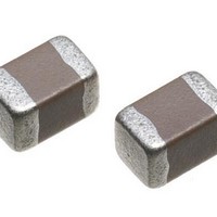
Multilayer Ceramic Capacitors (MLCC) - SMD/SMT 0805 3300pF 100volts C0G 5%
Manufacturer
TDK Corporation
Series
C2012r
Datasheet
1.C2012C0G2A332JT.pdf
(30 pages)
Specifications of C2012C0G2A332JT
Capacitance
3300 pF
Tolerance
5 %
Voltage Rating
100 Volts
Operating Temperature Range
- 55 C to + 125 C
Temperature Coefficient / Code
C0G (NP0)
Package / Case
0805 (2012 metric)
Product
General Type MLCCs
Dimensions
1.250 mm W x 2.000 mm L x 0.850 mm H
Termination Style
SMD/SMT
Lead Free Status / Rohs Status
Details
Other names
C2012C0G2A332J


TDK MLCC US Catalog
No.
16
17
*As for the initial measurement of capacitors (Class 2) on number 8, 12, 13, 14 and 15, leave capacitor at 150 –10, 0°C
for 1 hour and measure the value after leaving capacitor for 24±2h in ambient condition.
General
Specifications
Item
Moisture Resistance
External
appearance
Capacitance
Q (Class 1)
D.F. (Class 2)
Insulation
Resistance
Life
External
appearance
Capacitance
Q (Class 1)
D.F. (Class 2)
Insulation
Resistance
Performance
No mechanical damage.
200 min.
Characteristics
X7R: 200% of initial spec. max.
X7S: 200% of initial spec. max
X7T: 200% of initial spec. max
500MΩ or 25MΩ•μF min.
whichever smaller.
No mechanical damage.
350 min.
Characteristics
X7R: 200% of initial spec. max.
X7S: 200% of initial spec. max
X7T: 200% of initial spec. max
1,000MΩ or 50MΩ•μF min.
whichever smaller.
Characteristics
Class 1
Class 2
Characteristics
Class 1
Class 2
C0G
C0G
X7R
X7S
X7T
X7R
X7S
X7T
Change from the
value before test
±7.5 %
± 12.5 %
Change from the
value before test
±3 %
± 15 %
C Series – Mid Voltage Application
Page 100
Test or Inspection Method
Reflow solder the capacitors on P.C. board (shown in
Appendix 1a or Appendix 1b) before testing.
Apply the rated voltage at temperature 40±2ºC and 90
to 95%RH for 500 +24,0h.
Charge/discharge current shall not exceed 50mA.
Leave the capacitor in ambient conditions for 6 to 24h
(Class 1) or 24±2h (Class 2) before measurement.
Voltage conditioning (only for class 2):
Voltage treat the capacitors under testing temperature
and voltage for 1 hour.
Leave the capacitors in ambient condition for 24±2h
before measurement.
Use this measurement for initial value.
Reflow solder the capacitor on P.C. board (shown in
Appendix 1a or Appendix 1b) before testing.
Apply voltage at 125±2ºC for 1,000 +48, 0h.
Applied voltage is 1xRV. Some items may be tested at
higher voltage (1.2x, 1.5x or 2xRV).
Charge/discharge current shall not exceed 50mA.
Leave the capacitors in ambient condition for 6 to 24h
(Class 1) or 24±2h (Class 2) before measurement.
Voltage conditioning (only for class 2):
Voltage treat the capacitor under testing temperature
and voltage for 1 hour.
Leave the capacitor in ambient conditions for 24±2h
before measurement.
Use this measurement for initial value.
Version B11
Related parts for C2012C0G2A332JT
Image
Part Number
Description
Manufacturer
Datasheet
Request
R

Part Number:
Description:
TDK DC to DC Converters, DC to AC Inverters
Manufacturer:
TDK Corporation
Datasheet:
Part Number:
Description:
TDK DC to DC Converters, DC to AC Inverters
Manufacturer:
TDK Corporation
Datasheet: