T354E106M020AT Kemet, T354E106M020AT Datasheet - Page 11
T354E106M020AT
Manufacturer Part Number
T354E106M020AT
Description
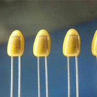
Tantalum Capacitors - Solid Leaded 20V 10uF 20%
Manufacturer
Kemet
Series
T354r
Datasheet
1.T356A475K010AS.pdf
(13 pages)
Specifications of T354E106M020AT
Capacitance
10 uF
Voltage Rating
20 Volts
Esr
2.9 Ohms
Tolerance
20 %
Termination Style
Radial
Operating Temperature Range
- 55 C to + 125 C
Dimensions
5.5 mm Dia. x 10.2 mm H
Lead Spacing
6.35 mm
Product
Tantalum Solid Standard Grade - Other Various
Package / Case
Case E
Lead Free Status / Rohs Status
Details


all requirements of EIA Standard RS-468. KEMET capacitors are wound on a precision made ARIS Reel Package. ARIS Ammo Package is also available.
F Dimensions:
0.100" ± .015
0.125" ± .015
0.200" ± .015
0.250" ± .015"
0.100 " ± .015 (3 leaded)
Tantalum Molded Radial – ARIS Specification (Automatic Radial Insertion System)
On polar devices, the positive (+) lead exits from container first.
* Lead spacings are 2.5mm (.098") center-to center
** Lead spacings are 5.0mm (.197") center-to-center.
On polar devices, the positive (+) lead exits from container first.
* Lead spacings are 2.5mm (.098") center-to-center (T350 A-H)
** Lead spacings are 5.0mm (.197") center-to-center
# Lead spacings are 6.35mm (.25") center-to-center
+ Lead spacings are 3.18mm (.125") center-to-center
Notes: (1) See page 50 for T330, page 53 for T340 and page 59 for T35X specific dimensions.
Tantalum Dipped Radial – ARIS Specification (Automatic Radial Insertion System)
Body Height (1)
Body Width (1)
Sprocket Hole
Diameter
Lead Diameter
Lead Center (5)
Component Base
to Tape Center (2)(4)(6)
Lead Standoff
Height
Component Height
Above Tape Center
Component Alignment
Front to Rear
Cut Out Length
Lead Protrustion
KEMET offers Solid Tantalum Capacitors fully compatible for use with automatic insertion machines for radial-lead components. Aris Reeling meets
Tantalum Molded Tape and Reel Dimensions in Millimeters & (Inches)
72
Dimension
(2) Reference Only
(3) Cumulative pitch error ± 1.0mm (.039") maximum in 20 consecutive sprocket hole locations.
(4) Measured at bottom of standoff.
(5) P, P1 and F measured at egress from carrier tape.
(6) H dimensions for T370 D and E 16.5mm ± 0.5mm (0.650" ± 0.020")
Notes: (1) See page 62 for T35X and page 69 for T39X specific dimensions.
Body Height (1)
Body Width (1)
Sprocket Hole
Diameter
Lead Diameter
Lead Center (4)
Component Base
to Tape Center (4)
Lead Standoff
Height
Component Height
Above Tape Center
Component Alignment
Front to Rear
Cut Out Length
Lead Protrustion
Dimension
(2) Cumulative pitch error ± 1.0mm (.039) maximum in 20 consecutive sprocket hole locations.
(3) Measured at bottom of standoff.
(4) P 1 and F measured at egress from carrier tape.
(5) P and P 2 measured at egress from carrier tape.
Tantalum Dipped Tape and Reel Dimensions in Millimeters & (Inches)
Symbol
A
A 1
D 0
d
F
H
H 0
H 1
Δ H
L
L 1
P1 Dimensions:
Lead
Spacing
0.100"
0.125"
0.200"
0.250"
0.100"
Symbol
A
A 1
D 0
d
F
H
H 0
H 1
Δ H
L
L 1
10.50 (.413)
15.24 (.600)
4.0 (.157)
0.51 or 0.64
(.020) (.025)
5.0
(.197) (.098)
(.630 - .827)
N/A
32.25 (1.270)
0
11.0 (.433)
2.0 (.079)
16.0 - 21.0
Nominal
mm (inch)
KEMET Electronics Corporation, P.O. Box 5928, Greenville, S.C. 29606 (864) 963-6300
–
–
–
–
–
17.0 (0.67)
10.2 (0.40)
4.0 (.157)
0.51 or 0.64
(.020) (.025)
See Note Below
C-7301
16.0 (.630) 18.0 (.709)
C-7301
16.0 (.630) 18.0 (.709)
32.25 (1.270)
0
11.0 (.433)
1.0 (.039)
0.200 ± .028"
0.187 ± .028"
0.150 ± .028"
0.125 ± .028"
0.100 ± .028" ( 3 leaded)
2.5
Nominal
mm (inch)
C-7303
C-7303
± .38 (±.015)
Maximum
Maximum ± .38
± (.015)
± 0.3 (± .012)
± 0.05 or ± .03
+ 0.8/ - 0.2
(+ .032/ -.008)
Reference Only
Maximum
± 2.0
(± .079)
Maximum
Maximum
(± .001)
Tolerance
mm (inch)
Maximum
Maximum
± 0.3 (±.012)
± 0.05 (.002)
C-7301
±0.5 (±.020) Minimum
C-7301
±0.5 (±.020) Minimum
Maximum
1.0 (.039)
Maximum
Maximum
Tolerance
mm (inch)
Component Pitch (5)
Sprocket Hole
Pitch (3)
Sprocket Hole
Center to Lead
Center (4) (5)
Sprocket Hole Center
to Component Center
Body Thickness
Total Tape Thickness
Carrier Tape Width
Hold-Down Tape
Width
Sprocket Hole
Location
Hold-Down Tape
Location
PACKAGING INFORMATION
Dimension
C-7303
C-7303
➀
➁
➂
➃
➄
T396/8*
T350/1*
T352/3/6**
T354#
T355+
Component Pitch (5)
Sprocket Hole
Pitch (2)
Sprocket Hole
Center to Lead
Center (3) (4)
Sprocket Hole Center
to Component (5)
Center
Body Thickness
Total Tape Thickness
Carrier Tape Width
Hold-Down Tape
Width
Sprocket Hole
Location
Hold-Down Tape
Location
Symbol
Dimension
➀
➁
➂
P
P 0
P 1
P 2
T 0
T
W
W 0
W 1
W 2
T370
T340**
T330**
W
12.7 (.500)
12.7 (.500)
3.85
(.152) (.188) (.201)
6.35 (.250)
6.35 (.250)
0.7 (0.28)
18.0 (.709)
15
(.561) (.236)
9.0 (.354)
3.0 or 12.0
(.118)
D
0
Nominal
mm (inch)
L
or
Symbol
4.76
d
(.472)
➀
P
P 0
P 1
P 2
T 0
T
W
W 0
W 1
W 2
W
6
5.1
T
12.7 (.500)
12.7 (.500)
See Note
Below
See Note
Below
10.2 (.400)
0.7 (0.28)
18.0 (.709)
15mm or 6mm
(.561)
9.0 (.354)
12mm (.472)
P
D
Nominal
mm (inch)
0
P
2
➁
± 1.0 (± .039)
± 0.3 (±.012)
± 0.7 (±.028)
± 1.3 (±.051)
± 1.3 Maximum
± .02 (±.008)
+ 1.0/-0.5
(+.039/-.020)
+ 1.0/-0.8
(+.039/.031)
+.075/-0.5
(+.030/-.020)
Maximum
F
➀
Tolerance
mm (inch)
(.236)
d
P
1
T
P
➂
± 1.0 (± .039)
± 0.3 (±.012)
± 0.7 (±.028)
Maximum
± .02 (.008)
+ 1.0/-0.5
(+.039/-.020)
+ 1.0/-0.8
(+.039/-.031)
+.075/-0.5
(+.030/-.020)
Maximum
A
H
P
P
Tolerance
mm (inch)
0
L
1
0
2
1
➁
F
A
P
1
W
W
W
2
2
0
➂
A
P
W
0
1
L
1
1
H
H
A
1
W
W
T
W
0
2
0
2
W
ΔH
Carrier
Tape
1MM Max.
(.039")
1
H
H
1
Related parts for T354E106M020AT
Image
Part Number
Description
Manufacturer
Datasheet
Request
R

Part Number:
Description:
CAP, KEMET #F601BL105K250C
Manufacturer:
Kemet
Datasheet:
Part Number:
Description:
Manufacturer:
Kemet
Datasheet:
Part Number:
Description:
Manufacturer:
Kemet
Datasheet: