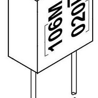
T370D106M020AS Kemet, T370D106M020AS Datasheet - Page 8

T370D106M020AS
Manufacturer Part Number
T370D106M020AS
Description
Tantalum Capacitors - Solid Leaded 20V 10uF 20%
Manufacturer
Kemet
Series
T370r
Datasheet
1.T322A335K010AS.pdf
(19 pages)
Specifications of T370D106M020AS
Capacitance
10 uF
Voltage Rating
20 Volts
Esr
2.9 Ohms
Tolerance
20 %
Termination Style
Radial
Operating Temperature Range
- 55 C to + 85 C
Dimensions
5.590 mm W x 2.79 mm H
Lead Spacing
4.570 mm
Product
Tantalum Solid Standard Grade - Other Various
Dissipation Factor Df
6
Leakage Current
2 uA
Package / Case
Case D
Lead Free Status / Rohs Status
No
KEMET T330 Series, polar-type, radial lead rectangular Precision
Molded Tantalum (PMT) capacitors are primarily designed for appli-
cations that demand full use of the premium space available in print-
ed circuitry and high density packaging. Compact, space saving
T330 Series capacitors provide superior packing factor and space
utilization compared with tubular units of the same microcoulomb
(CV) rating.
T330 Series capacitors employ a rectangular sintered, dry tantalum
anode, transfer molded in precision dies with a high impact resistant
plastic having excellent electrical, physical, and moisture resistant
properties. All cases utilize gold color plastic which permits laser
marking with outstanding permanency and legibility. The polarity is
indicated by a + sign permanently marked on the case. The radius on
the two vertical edges at the positive end of B, C, and D Cases can
be used as a sensing dimension for automatic insertion processes.
The compact space saving T340 Series is transfer molded in preci-
sion dies with a high impact resistant plastic having excellent elec-
trical, physical, and moisture resistant properties. The gold color
plastic case utilized permits laser marking with outstanding perma-
nency and legibility.
Marking is provided on the top of the case to allow visual inspection
for proper polarity and placement after insertion. In addition, positive
polarity identification is achieved by an easily recognized molded
radius on the positive end of the case. This physical polarity identifi-
cation is readily observed after capacitor placement as a further aid
to the top marking in prevention of possible reverse insertion.
• CAPACITANCE/VOLTAGE RANGE:
• CAPACITANCE TOLERANCE: Available in standard EIA nominal
• DISSIPATION FACTOR: Maximum DF limits are shown in corre-
• DC LEAKAGE CURRENT: Maximum leakage values at 25°C are
T330: 0.1-220µF, 6-50 Volts.
T340: 0.1-330µF, 6-50 Volts.
values with ±20% tolerance standard, ±10% and ±5% available
on special order.
sponding series part number listing. See Application Notes
Section, page 78.
shown in part number listings, pages 51, 52, 55, 56 and 57. See
Application Notes Section, page 76.
100.0
150.0
220.0
330.0
0.10
0.15
0.22
0.33
0.47
0.68
1.00
1.50
2.20
3.30
4.70
6.80
10.0
15.0
22.0
33.0
47.0
68.0
8.0
6.0
5.0
3.7
3.0
2.0
1.8
1.6
0.9
0.9
0.7
8.0
6.0
5.0
3.7
2.7
2.1
1.7
1.3
1.0
0.8
0.6
6.0
5.0
4.0
3.2
2.5
2.0
1.6
1.3
1.0
0.8
0.6
7.0
5.5
4.5
3.6
2.9
2.3
1.8
1.4
1.2
0.9
0.6
8.0
6.0
5.0
4.0
3.1
2.5
2.0
1.5
1.2
1.0
0.8
26.0
21.0
17.0
15.0
13.0
10.0
8.0
6.0
5.0
4.0
3.0
2.5
2.0
1.6
1.3
1.0
0.8
26.0
21.0
17.0
15.0
13.0
10.0
8.0
5.0
3.5
3.0
2.5
2.0
1.6
1.2
1.0
The location of the standoffs may serve a similar sensing function for
the A Case. These standoffs, located in the base of all case sizes,
provide vents for air circulation and also allow easy removal of flux
residues from leadwire and circuit board solder joints.
T330 Series capacitors are highly reliable and exhibit performance
characteristics typical of military test standards. They are available
in capacitance values ranging from 0.1 to 220 microfarads in ±20,
±10, ±5% tolerance levels, and in working voltages from 6 to 50
volts. At 85°C the capacitors will operate continuously at full rated
voltage. They are rated to 125°C when operated at 2/3 of nameplate
voltage. In addition, they feature exceptionally low DC leakage and
Dissipation Factor characteristics.
They are ideal for bypass, coupling, and timing applications in com-
puters, military ordinance, industrial, entertainment, and consumer
electronic equipment.
Standoffs, located in the base of all case sizes, provide vents for air
circulation and also allow easy removal of flux residues from lead-
wire and circuit board solder joints. With very low impedance and
ESR values, the T340 Series features exceptionally low DC leakage
and DF characteristics. The T340 Series is available in standard
±20%; ±10%; ±5% (special order) capacitance tolerance.
T340 Series capacitors are highly reliable and exhibit performance
characteristics typical of military test standards.
• RATED VOLTAGE; WORKING VOLTAGE; SURGE VOLTAGE;
• IMPEDANCE and ESR: See Application Notes Section, page 77
• AC RIPPLE VOLTAGE: Permissible AC ripple voltage is related to
• ENVIRONMENTAL CONSIDERATIONS:
• LEAD MATERIAL: Solder coated steel core with copper ply per
• LEAD TAPE and REEL: Reeling per specification RS-468. See
REVERSE VOLTAGE: See Application Notes Section, pages 76 &
77 for description.
& 78 for additional information. Reference ESR values are shown
in table below.
ESR of the capacitor and the power dissipation capabilities of a par-
ticular case size. Thermal capacities for the various case sizes
have been determined and are listed in Table below. For addi-
tional description see page 78.
A. Shock Test: MIL-STD-202, Method 213.
B. Thermal Shock, MIL-STD-202, Method 107.
C. Moisture Resistance: MIL-STD-202, Method 106.
D. Solderability: MIL-STD-202, Method 208.
For additional Environmental Test Information see pages 80, 81
and 82.
MIL-STD-1276.
pages 71 and 73 for additional information.
T330/T340
T330
T340 only
D/F
C
D
A
B
E
.100
.125
.125
.180
.09
.09
49


