AD698APZ Analog Devices Inc, AD698APZ Datasheet - Page 11
AD698APZ
Manufacturer Part Number
AD698APZ
Description
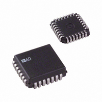
IC LVDT SIGNAL COND 28-PLCC
Manufacturer
Analog Devices Inc
Type
Signal Conditionerr
Datasheet
1.AD698APZ.pdf
(12 pages)
Specifications of AD698APZ
Input Type
Voltage
Output Type
Voltage
Interface
LVDT
Current - Supply
15mA
Mounting Type
Surface Mount
Package / Case
28-LCC (J-Lead)
Bandwidth
20kHz
Supply Voltage Min
13V
Supply Voltage Max
36V
Digital Ic Case Style
LCC
No. Of Pins
28
Operating Temperature Range
-40°C To +85°C
Msl
MSL 5 - 48 Hours
Supply Voltage Range
13V To 36V
Audio Ic Case Style
PLCC
Base Number
698
Rohs Compliant
Yes
Lead Free Status / RoHS Status
Lead free / RoHS Compliant
Lead Free Status / RoHS Status
Lead free / RoHS Compliant, Lead free / RoHS Compliant
Available stocks
Company
Part Number
Manufacturer
Quantity
Price
Company:

Part Number:
AD698APZ
Manufacturer:
Analog Devices Inc
Quantity:
135
Part Number:
AD698APZ
Manufacturer:
ADI/亚德诺
Quantity:
20 000


REV. B
Solving for V
Choose an oscillator amplitude that is in the range of 1 V to
3.5 V rms. For an input excitation level of 3 V rms, the output
signal from the amplifier gain stage will be 3.5 V rms 0.8 V or
2.4 V rms, which is in the acceptable range.
OUT
R
/V
S
= [400 – 1] R
IN
V
= 400 and setting R
OUT
RESISTORS,
INDUCTORS
OR CAPACITORS
R
Figure 20. AD698 Interconnection Diagram for AC Bridge Applications
G
2 R
R
+15V
–15V
G
A1
G
A2
R
R
/2 = 19.95 k
S
1
OP AMP
S
S
DUAL
6.8µF
V
G
IN
= 100
100nF
C2
C1
R1
then:
10
11
12
1
2
3
4
5
6
7
8
9
EXC1
EXC2
FREQ1
BFILT2
–AIN
–V
LEV1
FREQ2
BFILT1
–BIN
+BIN
LEV2
6.8µF
S
AD698
FEEDBACK
–11–
OFFSET2
OFFSET1
OUT FILT
–ACOMP
+ACOMP
SIG OUT
SIG REF
AFILT2
AFILT1
+AIN
Since A/B is known, the value of R2, the output FS resistor may
be chosen by the formula:
For a 10 V output at FS, with an A/B of 0.8; solve for R2.
This will result in a V
bridge. The other components, C1, C2, C3, C4 may be selected
by following the guidelines on general device operation men-
tioned earlier.
If a gain trim is required, then a trim resistor can be used to ad-
just either R2 or R
network on the OFFSET 1 and OFFSET 2 pins of the AD698.
+V
S
100nF
19
18
17
16
14
13
24
23
22
20
15
21
R4
R3
R2
C4
C3
LAG/LEAD
NETWORK
A
C
PHASE
1000pF
R2 = 10 V [0.8
REFERENCE
SIGNAL
B
D
V
G
V
OUT
. Bridge offsets should be adjusted by a trim
OUT
R
OUT
L
R
S
= A/B
PHASE LAG
PHASE LAG = Arc Tan (Hz RC);
PHASE LEAD = Arc Tan 1/(Hz RC)
WHERE R = R
A
C
of 10 V for a full-scale signal from the
R
T
C
B
D
500 A] = 25.0 k
R
500 A
S
S
// (R
S
+ R
C
A
PHASE LEAD
R
C
T
T
)
R2
B
D
R
C
S
AD698
Related parts for AD698APZ
Image
Part Number
Description
Manufacturer
Datasheet
Request
R

Part Number:
Description:
±1.7g Dual-Axis IMEMS Accelerometer Evaluation Board
Manufacturer:
Analog Devices Inc
Datasheet:

Part Number:
Description:
Inertial Sensor Evaluation System
Manufacturer:
Analog Devices Inc
Datasheet:
Part Number:
Description:
Manufacturer:
Analog Devices Inc
Datasheet:
Part Number:
Description:
Manufacturer:
Analog Devices Inc
Datasheet:
Part Number:
Description:
Manufacturer:
Analog Devices Inc
Datasheet:
Part Number:
Description:
Manufacturer:
Analog Devices Inc
Datasheet:
Part Number:
Description:
Manufacturer:
Analog Devices Inc
Datasheet:
Part Number:
Description:
Manufacturer:
Analog Devices Inc
Datasheet:
Part Number:
Description:
Manufacturer:
Analog Devices Inc
Datasheet:
Part Number:
Description:
Manufacturer:
Analog Devices Inc
Datasheet:
Part Number:
Description:
Manufacturer:
Analog Devices Inc
Datasheet:
Part Number:
Description:
Manufacturer:
Analog Devices Inc
Datasheet:
Part Number:
Description:
Manufacturer:
Analog Devices Inc
Datasheet: