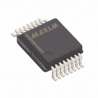
MAX1452AAE+ Maxim Integrated Products, MAX1452AAE+ Datasheet - Page 9

MAX1452AAE+
Manufacturer Part Number
MAX1452AAE+
Description
IC SENSOR SIGNAL COND 16-SSOP
Manufacturer
Maxim Integrated Products
Type
Signal Conditionerr
Datasheet
1.MAX1452CAE.pdf
(25 pages)
Specifications of MAX1452AAE+
Input Type
Analog
Output Type
Analog
Interface
Serial
Current - Supply
2.5mA
Mounting Type
Surface Mount
Package / Case
16-SSOP
Bandwidth
1.15MHz
Supply Voltage Min
4.5V
Supply Voltage Max
5.5V
Digital Ic Case Style
SSOP
No. Of Pins
16
Operating Temperature Range
-40°C To +125°C
Supply Voltage Range
4.5V To 5.5V
Rohs Compliant
Yes
Lead Free Status / RoHS Status
Lead free / RoHS Compliant
Nonratiometric output configuration enables the sensor
power to vary over a wide range. A high performance
voltage reference, such as the MAX15006B, is incorpo-
rated in the circuit to provide a stable supply and refer-
ence for MAX1452 operation. A typical example is
shown in Figure 3. Nonratiometric operation is valuable
when wide ranges of input voltage are to be expected
and the system A/D or readout device does not enable
ratiometric operation.
Process Control systems benefit from a 4–20mA current
loop output format for noise immunity, long cable runs,
and 2-wire sensor operation. The loop voltages can
range from 12VDC to 40VDC and are inherently nonra-
tiometric. The low current consumption of the MAX1452
allows it to operate from loop power with a simple
4–20mA drive circuit efficiently generated using the
integrated uncommitted op amp (Figure 4).
Figure 3. Basic Nonratiometric Output Configuration
Typical 2-Wire, Loop Powered,
(12VDC < VPWR < 40VDC)
4–20mA Operating Circuit
_______________________________________________________________________________________
Typical Nonratiometric
SENSOR
Operating Circuit
5
6
4
BDR
INP
INM
TEST V
8
MAX1452
V
SS
DD
7
3
FSOTC
V
ISRC
OUT
DDF
Low-Cost Precision Sensor
9
2
16
1
R
R
STC
ISRC
The MAX1452 has five 16-bit internal calibration regis-
ters that are loaded from EEPROM, or loaded from the
serial digital interface.
Data can be loaded into the internal calibration regis-
ters under three different circumstances.
Normal Operation, Power-On Initialization Sequence
•
•
•
•
•
Normal Operation, Continuous Refresh
•
•
•
•
1.0μF
30Ω
The MAX1452 has been calibrated, the Secure-
Lock byte is set (CL[7:0] = FFhex) and UNLOCK is
low.
Power is applied to the device.
The power-on-reset functions have completed.
Registers CONFIG, OTCDAC, and FSOTCDAC are
refreshed from EEPROM.
Registers ODAC, and FSODAC are refreshed from
the temperature indexed EEPROM locations.
The MAX1452 has been calibrated, the Secure-
Lock byte has been set (CL[7:0] = FFhex) and
UNLOCK is low.
Power is applied to the device.
The power-on-reset functions have completed.
The temperature index timer reaches a 1ms time
period.
2.2μF
8
OUT
Internal Calibration Registers (ICRs)
MAX15006B
Signal Conditioner
GND
5
IN
0.1μF
1
S
0.1μF
G
D
2N4392
+12V TO +40V
GND
VPWR
OUT
9


