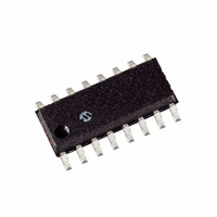
RE46C143S16F Microchip Technology, RE46C143S16F Datasheet

RE46C143S16F
Specifications of RE46C143S16F
Related parts for RE46C143S16F
RE46C143S16F Summary of contents
Page 1
... R&E International A Subsidiary of Microchip Technology Inc. RE46C143 CMOS Photoelectric Smoke Detector ASIC with Interconnect Product Specification General Description The RE46C143 is low power CMOS photoelectric type smoke detector IC. With minimal external components this circuit will provide all the required features for a photoelectric type smoke detector. ...
Page 2
... VDD=12V, Vin=VSS 16 VDD=12V, Vin=VSS 10 FEED=-10V VDD=12V, Vin=VDD, STROBE 1,2 active 3,12,15 VDD=12V, Vin=VDD 10 FEED=22V 16 Vin=VDD 7 Vin=VDD 7 Vin=17V, VDD=12 11,13 Output Off, Output=VSS 11,13 Output Off, Output=VDD R&E International A Subsidiary of Microchip Technology Inc. Limits Min Typ Max Units 5 6.2 4 ...
Page 3
... Local smoke, Push to Test or 1,2,3 Chamber Test, Note 1 - Internal Reference VDD=6V to 12V, STROBE Output 4 ST Voltage VDD=6V to 12V, IRED Output 6 Voltage 4,5 Active, VDD=6V to 12V 6,5 Active, VDD=6V to 12V R&E International A Subsidiary of Microchip Technology Inc. Limits Min Typ Max Units 5 -16 mA ...
Page 4
... IODMP Test From Start of Local Alarm IODLY1 Active IO pulse width guaranteed filtered Input, No Local IOFILT Alarm No Local Alarm, From IO Active 7 IODLY2 Horn Active R&E International A Subsidiary of Microchip Technology Inc. Limits Min Typ 9.4 10.5 Note 2 9.4 10 .67 LED IS NOT ON 9.7 10.5 2 ...
Page 5
... RE46C143 CMOS Photoelectric Smoke Detector ASIC with Interconnect Product Specification © 2009 Microchip Technology Inc. Functional Block Diagram Figure 1 R&E International A Subsidiary of Microchip Technology Inc. DS22178B-page 5 ...
Page 6
... This input is connected to a VDD reference voltage to set the low battery warning voltage. 16 TEST This input is used to invoke two test modes. This input has an internal pull-down. © 2009 Microchip Technology Inc. PIN DESCRIPTIONS DESCRIPTION R&E International A Subsidiary of Microchip Technology Inc. DS22178B-page 6 ...
Page 7
... C3 is typical for an alkaline battery. This capacitance should be increased to 4.7uF or greater for a carbon battery. 3. R10, R11 and C6 are typical values and may be adjusted to maximize sound pressure. © 2009 Microchip Technology Inc. Typical Application Figure 2 R&E International A Subsidiary of Microchip Technology Inc. DS22178B-page 7 ...
Page 8
... The interconnect input has a 500mS nominal digital filter. This allows for interconnection to other types of alarms (carbon monoxide for example) that may have a pulsed interconnect signal. © 2009 Microchip Technology Inc. R&E International A Subsidiary of Microchip Technology Inc. =.6931 * DS22178B-page 8 ...
Page 9
... The LED pin is used as a low battery indicator. For VDD above the low battery threshold the open drain NMOS is off. If VDD falls below the threshold the NMOS turns on. © 2009 Microchip Technology Inc. R&E International A Subsidiary of Microchip Technology Inc. Description DS22178B-page 9 ...
Page 10
... Chamber Test and Warning is Offset from Low Battery Test and Warning by 21.5 Seconds © 2009 Microchip Technology Inc. Timing Diagrams Standby, No Alarm (not to scale) T PER1 T ON2 T PLED1 Low Supply or Chamber Test Failure Low Battery Warning Chirp T HOF3 R&E International A Subsidiary of Microchip Technology Inc DS22178B-page 10 ...
Page 11
... IO Dump active only in local alarm, inactive if external alarm © 2009 Microchip Technology Inc. Timing Diagrams (continued) Local Alarm Timing (not to scale) T PER2 T PLED2 Horn Timing Local or Remote Alarm T T HON1 HOF1 Interconnect Timing T IODLY2 R&E International A Subsidiary of Microchip Technology Inc. No Alarm DS22178B-page 11 ...
Page 12
... PowerMate, PowerTool, REAL ICE, rfLAB, Select Mode, Total Endurance, TSHARC, WiperLock and ZENA are trademarks of Microchip Technology Incorporated in the U.S.A. and other countries. SQTP is a service mark of Microchip Technology Incorporated in the U.S.A. All other trademarks mentioned herein are property of their respective companies. ...


