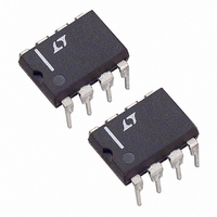
LT1025CN8 Linear Technology, LT1025CN8 Datasheet - Page 2

LT1025CN8
Manufacturer Part Number
LT1025CN8
Description
IC THERMO COMPNSATR MICRPWR 8DIP
Manufacturer
Linear Technology
Type
Thermocouple Conditionerr
Datasheet
1.LT1025CN8PBF.pdf
(12 pages)
Specifications of LT1025CN8
Input Type
Voltage
Output Type
Voltage
Current - Supply
150µA
Mounting Type
Through Hole
Package / Case
8-DIP (0.300", 7.62mm)
Lead Free Status / RoHS Status
Contains lead / RoHS non-compliant
Interface
-
Available stocks
Company
Part Number
Manufacturer
Quantity
Price
Company:
Part Number:
LT1025CN8
Manufacturer:
LT
Quantity:
5 510
Part Number:
LT1025CN8
Manufacturer:
LT/凌特
Quantity:
20 000
Company:
Part Number:
LT1025CN8#PBF
Manufacturer:
Linear Technology
Quantity:
1 875
Company:
Part Number:
LT1025CN8#PBF
Manufacturer:
VISHAY
Quantity:
12 592
Part Number:
LT1025CN8#PBF
Manufacturer:
LINEAR/凌特
Quantity:
20 000
(Note 1)
Input Supply Voltage .......................................... 36V
Output Voltage (Forced)........................................ 5V
Output Short-Circuit Duration ..................... Indefinite
Operating Temperature Range
Storage Temperature Range ............ – 55 C to 150 C
PARAMETER
Temperature Error at
10mV/ C Output (Notes 4, 5)
Resistor Divider Accuracy
(Notes 2, 4)
Supply Current
Line Regulation (Note 3)
Load Regulation (Note 3)
Divider Impedance
Change in Supply Current
LT1025
ABSOLUTE AXI U RATI GS
ELECTRICAL CHARACTERISTICS
temperature range, otherwise specificatons are at T
Note 1: Absolute Maximum Ratings are those values beyond which the
life of a device may be impaired.
Note 2: Divider accuracy is measured by applying a 10.000V signal to the
output divider and measuring the individual outputs.
Note 3: Regulation does not include the effects of self-heating. See
“Internal Temperature Rise” in Application Guide. Load regulation is
30 A I
2
LT1025AC, LT1025C ............................0 C to 70 C
LT1025AM, LT1025M .................. – 55 C to 125 C
O
1mA for T
A
W
0 C.
W W
CONDITIONS
T
Full Temperature Span
V
4V V
4V V
0 I
4V V
J
OUT
= 25 C
LT1025A
LT1025
LT1025A
LT1025
LT1025AC, LT1025C
LT1025AM, LT1025M
O
= 10mV/ C
IN
IN
IN
1mA
36V
36V
36V
U
A
= 25 C. V
The
E
J
K, T
R, S
E
J
K, T
R, S
E
J
K, T
R, S
S
= 5V, Pin 5 tied to Pin 4, unless otherwise noted.
denotes the specifications which apply over the full operating
PACKAGE/ORDER I FOR ATIO
Consult LTC Marketing for parts specified with wider operating temperature ranges.
Note 4: To calculate total temperature error at individual thermocouple
outputs, add 10mV/ C output error to the resistor divider error. Total error
for type K output at 25 C with an LT1025A is 0.5 C plus (0.4 V/ C)(25 C)/
(40.6 V/ C) = 0.5 C + 0.25 C = 0.75 C.
Note 5: Temperature error is defined as the deviation from the following
formula: V
term is a built-in nonlinearity designed to help compensate the nonlinearity
of the cold junction . This “bow” is 0.34 C for a 25 C temperature change.
60.9 V/ C
10mV/ C
GND
N8 PACKAGE
8-LEAD PDIP
V
T
V
T
IN
JMAX
JMAX
E
O
OUT
T
J8 PACKAGE 8-LEAD CERDIP
JMAX
1
2
3
4
= 10mV(T) + (10mV)(5.5 • 10
= 150 C,
= 150 C,
= 150 C,
TOP VIEW
Consider the N8 Package for Alternate Source
OBSOLETE PACKAGE
JA
JA
8-LEAD PLASTIC SO
= 130 C/W (N8)
JA
= 190 C/W (S8)
S8 PACKAGE
= 100 C/W
MIN
60.6
51.4
40.3
60.4
51.2
40.2
5.75
5.8
50
50
8
7
6
5
J
51.7 V/ C
K, T
40.6 V/ C
R, S
6 V/ C
R
COMMON
–
See Curve
0.003
U
60.9
51.7
40.6
5.95
60.9
51.7
40.6
5.95
0.04
0.01
TYP
0.3
0.5
2.5
2.1
4.4
3.8
80
-4
)(T – 25 C)
S8 PART MARKING
ORDER PART
LT1025ACN8
LT1025CN8
LT1025CS8
LT1025AMJ8
LT1025MJ8
W
NUMBER
MAX
61.3
52.1
41.0
61.6
52.3
41.2
0.02
0.05
100
150
200
2
0.5
2.0
6.2
6.3
0.2
1025
. The second
UNITS
U
1025fb
V/ C
V/ C
V/ C
V/ C
V/ C
V/ C
V/ C
V/ C
C/V
A/V
k
k
k
k
C
C
A
A
A
C


