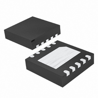
MAX6603ATB+T Maxim Integrated Products, MAX6603ATB+T Datasheet - Page 5

MAX6603ATB+T
Manufacturer Part Number
MAX6603ATB+T
Description
IC COND RTD-VOLT 10-TDFN
Manufacturer
Maxim Integrated Products
Type
Signal Conditionerr
Datasheet
1.MAX6603ATBT.pdf
(9 pages)
Specifications of MAX6603ATB+T
Input Type
Voltage
Output Type
Logic
Current - Supply
5.5mA
Mounting Type
Surface Mount
Package / Case
10-TDFN Exposed Pad
Lead Free Status / RoHS Status
Lead free / RoHS Compliant
Interface
-
Lead Free Status / Rohs Status
Lead free / RoHS Compliant
RS1+
RS2+
RS1-
RS2-
PIN
10
—
1
2
3
4
5
6
7
8
9
CLAMP
CLAMP
CLAMP
CLAMP
ESD
ESD
ESD
ESD
NAME
OUT1
OUT2
Functional Block Diagram
RS2+
RS1+
V
RS2-
RS1-
GND
V
DG1
DG2
V
CC
CC
EP
CC
R
R
SRC
SRC
_______________________________________________________________________________________
Dual-Channel, Platinum RTD-to-Voltage
I
I
EXC
EXC
Power-Supply Input. Bypass to GND with a 0.1µF capacitor as close to V
Sense Resistor 2 Negative Input
Sense Resistor 2 Positive Input
Sense Resistor 1 Positive Input
Sense Resistor 1 Negative Input
Ground
Diagnostic Output Signal 1. DG1 asserts low upon fault detection.
Output Analog Voltage 1. OUT1 is high impedance upon DG1 assertion.
Output Analog Voltage 2. OUT2 is high impedance upon DG2 assertion.
Diagnostic Output Signal 2. DG2 asserts low upon fault detection.
Exposed Pad. Connect to GND.
GND
V
DETECT
DETECT
CC
HI-V
HI-V
MAX6603
AMP
AMP
DETECT
DETECT
FAULT
FAULT
OUT1
DG1
OUT2
DG2
The MAX6603 converts a Deutsche Institute for Normung
(DIN) standard 200Ω Pt RTD to a high-level analog volt-
age without the need for external trims or precise dis-
crete components. The Pt RTD resistance conveys
temperature information approximated by the Callendar-
Van Dusen equation and is represented in Figure 1:
where:
The MAX6603 applies a constant excitation current of
1mA (typ) through the Pt RTD, generating a voltage
drop that is amplified and results in a high-level output
voltage. The excitation current (I
ratiometrically by 0.2mA/V (typ) with respect to V
and therefore, the amplified signal is ratiometric to the
power supply. The voltage amplification from input to
output is 5 (typ). The output voltage is applied to a
ratiometric ADC to produce a digital value independent
of supply voltage. For ADCs that use V
ence voltage, sudden changes in the supply voltage do
not affect the microcontroller’s reading of the tempera-
ture. Ratiometricity simplifies the connection to most
FUNCTION
R(T) = Resistance of Pt RTD at temperature (T)
R
T = Temperature in °C
A = 3.9083 E-3 °C
B = -5.7750 E-7 °C
C = 0 (approximation for temperatures > 0°C)
(Alpha coefficients can vary depending on
standards.)
Signal Conditioner
0
R(T) = R
= Base resistance in ohms at 0°C
O
Detailed Description
[1 + AT + BT
CC
-1
-2
as possible.
(alpha coefficient 1)
Pin Description
(alpha coefficient 2)
EXC
2
+ CT
) typically varies
CC
3
]
as their refer-
CC
5
,


