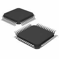
MAX9257GCM/V+ Maxim Integrated Products, MAX9257GCM/V+ Datasheet - Page 27

MAX9257GCM/V+
Manufacturer Part Number
MAX9257GCM/V+
Description
IC SER/DESER PROG 48-LQFP
Manufacturer
Maxim Integrated Products
Datasheet
1.MAX9257GTL.pdf
(52 pages)
Specifications of MAX9257GCM/V+
Function
Serializer/Deserializer
Data Rate
840Mbps
Input Type
Serial
Output Type
LVDS
Number Of Inputs
16
Number Of Outputs
1
Voltage - Supply
3 V ~ 3.6 V
Operating Temperature
-40°C ~ 105°C
Mounting Type
Surface Mount
Package / Case
48-LQFP
Lead Free Status / RoHS Status
Lead free / RoHS Compliant
The LOCK and ERROR outputs can be wired in an
AND configuration if you have multiple serializers and
deserializers, or a single serializer fanned out to multi-
ple deserializers through a repeater. For such situa-
tions, wire the multiple LOCK outputs together and use
a single pullup resistor to pull up all the lines high.
LOCK is high if all the devices are locked. Do the same
thing for ERROR; ERROR is low if any MAX9258 reports
errors.
In the control channel phase, there are two modes: base
and bypass. In base mode, ECU always communicates
using the MAX9257/MAX9258 UART protocol and com-
munication with a peripheral device is performed in I
by the MAX9257. Packets not addressed to the
MAX9257 or the MAX9258 get converted to I
passed to the peripheral device. Similarly, I
from the peripheral device get converted to UART pack-
ets in the reverse direction. ECU can disable communi-
cation to the peripheral device by writing a 0 to INTEN
(REG8[6] in the MAX9257 and REG7[6] in the MAX9258).
Base mode is the default mode. Bypass mode is entered
by writing a 0 to INTMODE and 1 to INTEN (Table 23).
Bypass mode is exited if there is no activity from ECU in
the control channel for the duration of CTO. When CTO
times out, INTEN reverts back to 0 and MAX9257/
MAX9258 revert back to base mode. To permanently
stay in bypass mode, ECU can lock the CTO timer or
program CTO to be longer than ETO and STO.
Table 21. Preemphasis
Table 22. GPIOs vs. Parallel-Word Width
000,101,110
REG12[7:5]
PARALLEL-WORD
Base Mode and Bypass Mode (Basics)
001
010
011
100
111
WIDTH (N)
18
16
14
12
10
Fully Programmable Serializer/Deserializer
______________________________________________________________________________________
PREEMPHASIS (%)
GPIOs AVAILABLE
100
20
40
60
80
0
GPIO[8:9]
GPIO[6:9]
GPIO[4:9]
GPIO[2:9]
GPIO[0:9]
with UART/I
2
C packets
2
C and
2
C
The MAX9257/MAX9258 feature three different timers.
The start timeout (STO) and end timeout (ETO) control
the duration of the control channel. The come-back
timeout (CTO) controls the duration of bypass mode.
The STO (start timeout) timer closes the control channel if
the ECU does not start using the control channel within
the STO timeout period. The STO timer is configured by
Table 23. Selection of Base Mode or
Bypass Mode
Table 24. STO Clock Divide Ratio
MAX9257 REG8[6],
MAX9258 REG7[6]
INTEN
2
0
1
1
REG2[7:4]
C Control Channel
00XX
0100
0101
0110
0111
1000
1001
1010
1011
1100
1101
1110
1111
MAX9257 REG8[7],
MAX9258 REG7[7]
INTMODE
X
1
0
STODIV
16,384
32,768
Base mode,
communication
with peripheral is
not enabled
Base mode,
communication
with peripheral is
enabled (I
Bypass mode,
communication
with MAX9257/
MAX9258 is not
enabled,
communication
with peripheral is
enabled (UART)
1024
2048
4096
8192
128
256
512
16
16
32
64
STO Timer
MODE
Timers
2
C)
27


