DS15BR401TSQX/NOPB National Semiconductor, DS15BR401TSQX/NOPB Datasheet - Page 5
DS15BR401TSQX/NOPB
Manufacturer Part Number
DS15BR401TSQX/NOPB
Description
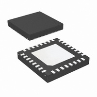
IC BUFFER LVDS 4CH 32-LLP
Manufacturer
National Semiconductor
Type
Bufferr
Datasheet
1.DS15BR400TSQNOPB.pdf
(14 pages)
Specifications of DS15BR401TSQX/NOPB
Tx/rx Type
LVDS
Delay Time
1.0ns
Capacitance - Input
3pF
Voltage - Supply
3 V ~ 3.6 V
Current - Supply
215mA
Mounting Type
Surface Mount
Package / Case
32-LLP
Number Of Elements
4
Number Of Receivers
4
Number Of Drivers
4
Input Type
CMOS
Operating Supply Voltage (typ)
3.3V
Differential Input High Threshold Voltage
100mV
Diff. Input Low Threshold Volt
-100mV
Output Type
Repeater
Differential Output Voltage
500mV
Transmission Data Rate
2000Mbps
Propagation Delay Time
2ns
Operating Temp Range
-40C to 85C
Operating Temperature Classification
Industrial
Mounting
Surface Mount
Pin Count
32
Lead Free Status / RoHS Status
Lead free / RoHS Compliant
Other names
DS15BR401TSQX


LVDS OUTPUT DC SPECIFICATIONS (OUTn±)
V
ΔV
V
ΔV
C
I
SUPPLY CURRENT (Static)
I
I
SWITCHING CHARACTERISTICS—LVDS OUTPUTS
t
t
t
t
t
t
t
t
t
t
Symbol
OS
CC
CCZ
LHT
HLT
PLHD
PHLD
SKD1
SKCC
SKP
JIT
ON
OFF
OD
OS
OUT
Note 5: Typical parameters are measured at V
Note 6: Differential output voltage V
Note 7: Output offset voltage V
Note 8: Jitter is not production tested, but guaranteed through characterization on a sample basis.
Note 9: Random Jitter, or RJ, is measured RMS with a histogram including 1500 histogram window hits. Stimulus and fixture Jitter has been subtracted. The
input voltage = V
Note 10: Deterministic Jitter, or DJ, is a peak to peak value. Stimulus and fixture jitter has been subtracted. The input voltage = V
mode voltage = V
Note 11: Total Jitter, or TJ, is measured peak to peak with a histogram including 3500 window hits. Stimulus and fixture Jitter has been subtracted. The input
voltage = V
Note 12: Not production tested. Guaranteed by a statistical analysis on a sample basis at the time of characterization.
OD
OS
Differential Output Voltage,
0% Pre-emphasis
Change in V
Complementary States
Offset Voltage
Change in V
Complementary States
LVDS Output Capacitance
Output Short Circuit Current
Supply Current
Supply Current - Power Down
Mode
Differential Low to High
Transition Time
Differential High to Low
Transition Time
Differential Low to High
Propagation Delay
Differential High to Low
Propagation Delay
Pulse Skew
Output Channel to Channel
Skew
Part to Part Skew
Jitter (0% Pre-emphasis)
(Note
LVDS Output Enable Time
LVDS Output Disable Time
ID
= 500 mV, input common mode voltage = V
ID
(Note
8)
ICM
= 500 mV, input common mode voltage = V
Parameter
= 1.2V, K28.5 pattern at 1.5 Gbps, t
12)
OD
OS
(Note
(Note
between
between
(Note
(Note
OS
(Note
(Note
12)
is defined as the average of the LVDS single-ended output voltages at logic high and logic low states.
7)
OD
12)
12)
is defined as ABS(OUT+–OUT−). Differential input voltage V
12)
6)
DD
R
Figure 1
OUT+ or OUT− to V
OUT+ or OUT− Short to GND
OUT+ or OUT− Short to VDD
All inputs and outputs enabled and active, terminated with
differential load of 100Ω between OUT+ and OUT-. PEM =
L
PWDN = L, PEM = L
Use an alternating 1 and 0 pattern at 200 Mbps, measure
between 20% and 80% of V
Figures 2, 4
Use an alternating 1 and 0 pattern at 200 Mbps, measure
at 50% V
Figures 2, 3
|t
Difference in propagation delay (t
output channels.
Common edge, parts at same temp and V
RJ - Alternating 1 and 0 at 750 MHz
DJ - K28.5 Pattern, 1.5 Gbps
TJ - PRBS 2
Time from PWDN to OUT± change from TRI-STATE to
active. Figures 5, 6
Time from PWDN to OUT± change from active to TRI-
STATE. Figures 5, 6
PLHD
L
= 3.3V, T
= 100Ω external resistor between OUT+ and OUT−
–t
PHLD
r
ICM
= t
OD
A
f
= 25°C. They are for reference purposes, and are not production-tested.
= 1.2V, 2
= 50 ps (20% to 80%). The K28.5 pattern is repeating bit streams of (0011111010 1100000101).
|
between input to output.
ICM
23
-1 Pattern, 1.5 Gbps
= 1.2V, 50% duty cycle at 750 MHz, t
23
-1 PRBS pattern at 1.5 Gbps, t
SS
Conditions
5
OD
(Note
.
PLHD
(Note
10)
(Note
or t
PHLD
11)
CC
ID
9)
is defined as ABS(IN+–IN−).
r
r
= t
) among all
= t
f
f
= 50 ps (20% to 80%).
= 50 ps (20% to 80%).
1.05
Min
250
−35
−35
ID
= 500 mV, input common
(Note
1.18
Typ
360
−21
175
170
170
2.5
1.0
1.0
0.5
20
10
25
14
14
5)
6
1.475
Max
500
−40
215
200
250
250
550
www.national.com
2.0
2.0
1.5
35
35
40
60
75
30
31
20
12
Units
mV
mV
mV
mA
mA
mA
pF
µA
ps
ps
ns
ns
ps
ps
ps
ps
ps
ps
µs
ns
V
Related parts for DS15BR401TSQX/NOPB
Image
Part Number
Description
Manufacturer
Datasheet
Request
R

Part Number:
Description:
National Semiconductor [8-Bit D/A Converter]
Manufacturer:
National Semiconductor
Datasheet:
Part Number:
Description:
National Semiconductor [Media Coprocessor]
Manufacturer:
National Semiconductor
Datasheet:
Part Number:
Description:
Digitally Controlled Tone and Volume Circuit with Stereo Audio Power Amplifier, Microphone Preamp Stage and National 3D Sound
Manufacturer:
National Semiconductor
Datasheet:
Part Number:
Description:
Digitally Controlled Tone and Volume Circuit with Stereo Audio Power Amplifier, Microphone Preamp Stage and National 3D Sound
Manufacturer:
National Semiconductor
Datasheet:
Part Number:
Description:
AC97 Rev 2 Codec with Sample Rate Conversion and National 3D Sound
Manufacturer:
National Semiconductor
Part Number:
Description:
Manufacturer:
National Semiconductor
Datasheet:
Part Number:
Description:
Manufacturer:
National Semiconductor
Datasheet:
Part Number:
Description:
General Purpose, Low Voltage, Low Power, Rail-to-Rail Output Operational Amplifiers
Manufacturer:
National Semiconductor
Datasheet:
Part Number:
Description:
8-bit 20 MSPS flash A/D converter.
Manufacturer:
National Semiconductor
Datasheet:
Part Number:
Description:
Low Noise Quad Operational Amplifier
Manufacturer:
National Semiconductor
Datasheet:
Part Number:
Description:
Quad Differential Line Receivers
Manufacturer:
National Semiconductor
Datasheet:
Part Number:
Description:
Quad High Speed Trapezoidal? Bus Transceiver
Manufacturer:
National Semiconductor
Datasheet:
Part Number:
Description:
Dual Line Receiver
Manufacturer:
National Semiconductor
Datasheet:
Part Number:
Description:
TTL to 10k ECL Level Translator with Latch
Manufacturer:
National Semiconductor
Datasheet: