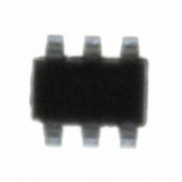
LX7202-15ISF Microsemi Analog Mixed Signal Group, LX7202-15ISF Datasheet - Page 2

LX7202-15ISF
Manufacturer Part Number
LX7202-15ISF
Description
IC USB LINE TERM EMI/ESD SOT23-6
Manufacturer
Microsemi Analog Mixed Signal Group
Type
USBr
Datasheet
1.LX7202-15ISF.pdf
(7 pages)
Specifications of LX7202-15ISF
Number Of Terminations
2
Voltage - Supply
5.25V
Operating Temperature
-40°C ~ 125°C
Mounting Type
Surface Mount
Package / Case
SOT-23-6
Lead Free Status / RoHS Status
Contains lead / RoHS non-compliant
Copyright © 2002
Rev. 1.0d, 2007-04-11
Unless otherwise specified, the following specifications apply over the operating ambient temperature -40°C
otherwise noted.
Steady State Power ...........................................................................100mW
ESD Air Discharge per IEC61000-4-2.................................................16KV
ESD Contact Discharge per IEC61000-4-2 .........................................10KV
Lead Soldering Temperature (10 Seconds) ........................................ 260°C
Operating Temperature ...................................................... -40°C to +125°C
Storage Temperature Range............................................... -55°C to +150°C
Note: Exceeding these ratings could cause damage to the device. All voltages are with
Junction Temperature Calculation: T
The θ
of the above assume no ambient airflow.
DOUT
VBUS
Name
GND
Stand-Off Voltage
Breakdown Voltage
Leakage Current
Series Resistance (-15)
Series Resistance (-22)
Temperature Coefficient of R
Pull Up Resistance
Capacitor
Total Capacitance
SF
DIN
THERMAL RESISTANCE
THERMAL RESISTANCE
JA
respect to
numbers are guidelines for the thermal performance of the device/pc-board system. All
TM
Plastic SOT-23 6-Pin
Parameter
Bus Voltage
Data In
Ground
Data Out
A B S O L U T E M A X I M U M R A T I N G S
Ground. Currents are positive into, negative out of specified terminal
11861 Western Avenue, Garden Grove, CA. 92841, 714-898-8121, Fax: 714-893-2570
T H E R M A L D A T A
-
-
JUNCTION TO
JUNCTION TO
J
S
= T
A
+ (P
Symbol
E L E C T R I C A L C H A R A C T E R I S T I C S
F U N C T I O N A L P I N D E S C R I P T I O N
T
VR
C
D
COEFF
R
V
R
R
I
C
TOT
x θ
BR
R
PU
WM
C
A
S
S
MBIENT
JA
ASE
).
, θ
IR = 1mA
VRWM = 5.25V, T = 25°C
Each Line
Each Line
Each Line
Each Line
Each Line
Between I/O Pins and Ground, Each Device
VR = 0V, f = 1MHz
JC
, θ
Analgo Mixed Signal Group
®
JA
Microsemi
EMI Filter & ESD Protection for Up Stream USB
Test Conditions
Description
62 °C/W
96 °C/W
.
P
RODUCTION
connector
connector
Ports
P A C K A G E P I N O U T
V
BUS
D
from
D
from
D
IN
IN
ATA
13.5
19.8
1.35
Min
54
6
1
2
3
≤
S
SF P
LX7202-xx
T
HEET
(Top View)
A
ACKAGE
≤
Typ
200
1.5
47
15
22
60
+125°C except where
LX7202-xx
Max
5.25
16.5
24.2
1.65
66
6
5
4
1
GND
D
to IC
D
to IC
OUT
OUT
Units
ppm
K Ω
µA
pF
pF
Ω
Ω
V
V
Page 2


