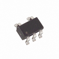
MAX3408EUK+T Maxim Integrated Products, MAX3408EUK+T Datasheet - Page 5

MAX3408EUK+T
Manufacturer Part Number
MAX3408EUK+T
Description
IC TERMINATION NETWORK SOT23-5
Manufacturer
Maxim Integrated Products
Type
Cabler
Datasheet
1.MAX3408EUKT.pdf
(6 pages)
Specifications of MAX3408EUK+T
Number Of Terminations
1
Voltage - Supply
4.5 V ~ 5.5 V
Operating Temperature
-40°C ~ 85°C
Mounting Type
Surface Mount
Package / Case
SOT-23-5, SC-74A, SOT-25
Lead Free Status / RoHS Status
Lead free / RoHS Compliant
Table 1. Termination Mode Selection
This is the voltage that would be reflected from any line
termination. As ZL becomes equal to Z0, this quantity
becomes zero. Often this is expressed in dB and is
called return loss. Reflection coefficient values less
than 0.1 corresponding to a return loss of -20dB are
generally seen as adequate. The MAX3406/MAX3407/
MAX3408 will typically provide reflection coefficients
below 0.01 or -40dB return loss.
In most cases, Z0 and ZL are considered real resistive
quantities and the result is a dimensionless scalar
quantity, but the equation is valid in the complex case
as well.
The MAX3406/MAX3407/MAX3408 resistance is con-
stant over temperature. The typical temperature coeffi-
cient of resistance is 150ppm/°C. Over a -40°C to
+85°C range centered at +25°C, this would be a ±1%
change in resistance. The initial accuracy at room tem-
perature is ±1.5%. This provides improved perfor-
Figure 1. Simplified Block Diagram
A
B
MAX3406EUK
MAX3407EUK
MAX3408EUK
PART
R1
_______________________________________________________________________________________
Resistance vs. Temperature
75Ω/100Ω/120Ω Switchable Termination
ENABLE = 1
ENABLE
R
AB
100
75
75
(Ω)
R2
MAX3406
MAX3407
MAX3408
ENABLE = 0
R
GND
AB
V
100
120
120
CC
(Ω)
mance over discrete 5% resistors with a 100ppm temp-
co, which are typically used for termination, ±5.6%
worst case. The reflections from such a mistermination
are minimal and correspond to a worst-case reflection
coefficient for the MAX3406/MAX3407/MAX3408 of
±0.015 or a -36dB return loss.
The MAX3406/MAX3407/MAX3408 accept input volt-
ages (V
resistance variation over this range (0.02% typically).
The initial accuracy specifications in the data sheet
already account for resistance variations of the signal
voltage range.
As seen in the Typical Operating Characteristics, there
is a slight impedance variation in the MAX3406/
MAX3407/MAX3408 with frequency. The reactive com-
ponents are parasitic inductance and capacitance
associated with packaging, lead frame, and bond
wires. These impedance components are very small up
to frequencies above 20MHz. These parasitics are also
similar to those that would be present with a discrete
resistor terminator, and they can generally be ignored.
These effects should be evaluated for applications with
significant frequency content above 20MHz. This
applies to sine wave sources above 20MHz and square
and video sources above 8MHz. For all intended appli-
cations, E1/T1, Standard Video, etc. they can be
ignored.
The V
be decoupled with a 0.1µF ceramic capacitor to GND
placed as close to the device as possible. This is
required for proper operation of the part.
TRANSISTOR COUNT: 102
PROCESS: BiCMOS
CC
AB
pin for the MAX3406/MAX3407/MAX3408 must
Resistance vs. Input Voltage Range
) from -3.6V to +3.6V. There is virtually no
Impedance vs. Frequency
Chip Information
Networks
Decoupling V
CC
5


