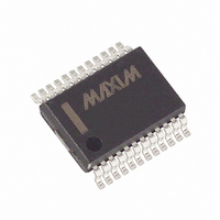
MXL1344ACAG+T Maxim Integrated Products, MXL1344ACAG+T Datasheet - Page 9

MXL1344ACAG+T
Manufacturer Part Number
MXL1344ACAG+T
Description
IC CABLE TERM MP 24-SSOP
Manufacturer
Maxim Integrated Products
Type
Cabler
Datasheet
1.MXL1344ACAG.pdf
(12 pages)
Specifications of MXL1344ACAG+T
Number Of Terminations
6
Voltage - Supply
4.5 V ~ 5.5 V
Operating Temperature
0°C ~ 70°C
Mounting Type
Surface Mount
Package / Case
24-SSOP
Lead Free Status / RoHS Status
Lead free / RoHS Compliant
Figure 8. Typical V.35 Interface
Figure 9. V.35 Termination and Internal Resistance Networks
MAX3175. With this cable wiring, the multiprotocol seri-
al port is set in RS-530A DTE mode
A standard V.11 interface is shown in Figure 6. For
high-speed data transmission, the V.11 specification
recommends terminating the cable at the receiver with
a 100Ω (min) resistor. The resistor, although not
required, prevents reflections from corrupting transmit-
ted data.
In Figure 7, the MXL1344A is used to terminate the V.11
receiver on the MXL1543. Internal to the MXL1344A, S1
is closed and S2 is open to present a 104Ω typical dif-
ferential resistance and high-Z common-mode imped-
ance. The MXL1543's internal V.28 termination is
disabled by opening S3.
_______________________________________________________________________________________
+5V Multiprotocol, Software-Selectable
A′
B′
C′
50Ω
50Ω
S1
GENERATOR
R1
52Ω
R2
52Ω
125Ω
S2
V.11 Termination
(Table 1).
MXL1344A
127Ω
R3
A
B
C
INTERCONNECTING
A
B
BALANCED
CABLE
GND
S3
The V.11 specification allows for signals with common-
mode variations of ±7V and differential signal ampli-
tudes from 2V to 6V with data rates as high as 10Mbps.
The MXL1344A maintains termination impedance
between 100Ω and 110Ω over these conditions.
Figure 8 shows a standard V.35 interface. The genera-
tor and the load must both present a 100Ω ±10Ω differ-
ential impedance and a 150Ω ±15Ω common-mode
impedance. The V.35 driver generates a current output
(±11mA typ) that develops an output voltage between
440mV and 660mV across the load termination net-
works.
In Figure 9, the MXL1344A is used to implement the
resistive T-network that is needed to properly terminate
R8
5kΩ
30kΩ
30kΩ
R5
R4
A′
B′
C′
10kΩ
10kΩ
R6
R7
Cable Terminator
TERMINATION
CABLE
125Ω
RECEIVER
LOAD
MXL1543
50Ω
50Ω
RECEIVER
V.35 Termination
9


