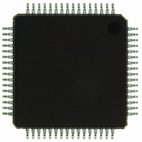
ISP1520BDGA ST-Ericsson Inc, ISP1520BDGA Datasheet - Page 6

ISP1520BDGA
Manufacturer Part Number
ISP1520BDGA
Description
IC USB HUB CONTROLLER HS 64-LQFP
Manufacturer
ST-Ericsson Inc
Datasheet
1.ISP1520BDUM.pdf
(54 pages)
Specifications of ISP1520BDGA
Applications
USB Hub/Microcontroller
Interface
I²C
Package / Case
64-LQFP
Mounting Type
Surface Mount
Lead Free Status / RoHS Status
Lead free / RoHS Compliant
Voltage - Supply
-
Other names
568-1169
ISP1520BD,551
ISP1520BD-S
ISP1520BD,551
ISP1520BD-S
Available stocks
Company
Part Number
Manufacturer
Quantity
Price
Philips Semiconductors
ISP1520_4
Product data sheet
Table 2.
Symbol
GND
V
TEST_HIGH
V
GND
DM1
DP1
TEST_LOW
TEST_HIGH
OC1_N
PSW1_N
GND
GND
V
V
OC4_N
PSW4_N
OC3_N
PSW3_N
OC2_N
PSW2_N
RESET_N
ADOC
CC4
CC2
CC3
REF(5V0)
[1][2]
Pin description
Pin
10
11
12
13
14
15
16
17
18
19
20
21
22
23
24
25
26
27
28
29
30
31
32
Type
-
-
-
-
-
AI/O
AI/O
-
-
AI/I
I/O
-
-
-
-
AI/I
I/O
AI/I
I/O
AI/I
I/O
I
I
Rev. 04 — 28 April 2006
…continued
Description
ground supply
supply voltage 4 (3.3 V) (crystal and PLL)
test pin; connect to 3.3 V
supply voltage 2 (3.3 V) (transceiver)
ground supply
downstream facing port 1 D− connection (analog)
downstream facing port 1 D+ connection (analog)
connect to GND
connect to 5.0 V through a 10 kΩ resistor
overcurrent sense input for downstream facing port 1
(analog/digital)
output — power switch control output (open-drain) with an
internal pull-up resistor for downstream facing port 1
input — function of the pin when used as an input is given in
Table 5
ground supply
ground supply
supply voltage 3 (3.3 V) (digital)
reference voltage (5 V ± 5 %); used to power internal pull-up
resistors of PSWn_N pins and also for the analog overcurrent
detection
overcurrent sense input for downstream facing port 4
(analog/digital)
output — power switch control output (open-drain) with an
internal pull-up resistor for downstream facing port 4
input — function of the pin when used as an input is given in
Table 5
overcurrent sense input for downstream facing port 3
(analog/digital)
output — power switch control output (open-drain) with an
internal pull-up resistor for downstream facing port 3
input — function of the pin when used as an input is given in
Table 5
overcurrent sense input for downstream facing port 2
(analog/digital)
output — power switch control output (open-drain) with an
internal pull-up resistor for downstream facing port 2
input — function of the pin when used as an input is given in
Table 5
asynchronous reset input; when reset is active, the internal
switch to the 1.5 kΩ external resistor is opened, and all pins
DPn and DMn are 3-state; it is recommended that you connect
to any one of the 3.3 V V
the schematics in ISP1520 Hub Demo Board User’s Guide
analog or digital overcurrent detect selection input; LOW selects
digital mode and HIGH (3.3 V or 5.0 V) selects analog mode
CC
pins through an RC circuit; refer to
© Koninklijke Philips Electronics N.V. 2006. All rights reserved.
Hi-Speed USB hub controller
ISP1520
[3]
[3]
5 of 53


