536254-4 TE Connectivity, 536254-4 Datasheet - Page 2
536254-4
Manufacturer Part Number
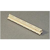
536254-4
Description
High Speed / Modular Connectors 100 VT RC BD BD 30AU 48
Manufacturer
TE Connectivity
Series
Micro-Strip Connectorsr
Specifications of 536254-4
Product Type
Receptacles
Number Of Rows
1
Number Of Positions / Contacts
10
Mounting Angle
Vertical
Pitch
4.06 mm
Mounting Style
Through Hole
Termination Style
Solder
Housing Material
Thermoplastic
Contact Material
Phosphor Bronze
Contact Plating
Gold
Mount Angle
Vertical
Termination Method To Pc Board
Through Hole - Solder
Pcb Mount Retention
Without
Guides
Without
Flame Retardant
Yes
Bus Bar Material
Phosphor Bronze
Tail Length (mm [in])
3.18 [0.125]
Bus Bar Mating Area Plating
Gold (30)
Bus Bar Termination Area Plating
Tin-Lead with Nickel underplated
Number Of Positions
100
Signal Contact Material
Phosphor Bronze
Signal Contact Mating Area Plating
Gold (30)
Signal Contact Termination Area Plating
Tin-Lead with Nickel underplated
Connector Style
Receptacle
Stack Height (mm [in])
10.92 [0.430], 18.75 [0.738]
Rohs/elv Compliance
ELV compliant, 5 of 6 Compliant
Lead Free Solder Processes
Wave solder capable to 240°C, Wave solder capable to 260°C, Wave solder capable to 265°C
Lead Free Status / Rohs Status
No
Available stocks
Company
Part Number
Manufacturer
Quantity
Price
Company:

Part Number:
536254-4
Manufacturer:
TE Connectivity AMP Connectors
Quantity:
516
Company:
Part Number:
536254-4
Manufacturer:
TYCO
Quantity:
35 808


3.4.
3.5.
Exam ination of product.
Term ination resistance, dry circuit.
Dielectric withstanding voltage.
Insulation resistance.
Tem perature rise vs current.
Vibration, random .
Physical shock.
Rev A
Perform ance and Test Description
Product is designed to m eet electrical, m echanical and environm ental perform ance requirem ents
specified in Figure 1. All tests are perform ed at am bient environm ental conditions per Test Specification
109-1 unless otherwise specified.
Test Requirem ents and Procedures Sum m ary
Test Description
Vertical signal:
Meets requirem ents of product
drawing and Application
Specification 114-11005.
20 m illiohm s m axim um initial.
ÄR 7 m illiohm s m axim um .
Ground bus:
10 m illiohm s m axim um initial.
ÄR 4 m illiohm s m axim um .
Right angle signal:
25 m illiohm s m axim um initial.
ÄR 7 m illiohm s m axim um .
Extended M-bus signal:
40 m illiohm s m axim um initial.
ÄR 7 m illiohm s m axim um .
500 vac at sea level.
No breakdown or flashover.
5000 m egohm s m inim um .
30 C m axim um tem perature rise at
specified current.
No discontinuities greater than 1
m icrosecond.
See Note.
No discontinuities greater than 1
m icrosecond.
See Note.
Figure 1 (continued)
MECHANICAL
ELECTRICAL
Requirem ent
Test between adjacent signal
Visual, dim ensional and functional
per applicable quality inspection
plan.
Subject m ated contacts assem bled
in housing to 50 m v open circuit at
100 m a m axim um .
See Figure 4.
TE Spec 109-6-1.
Test between adjacent signal
contacts and between signal
contacts and ground contacts of
m ated connector assem blies.
TE Spec 109-29-1.
contacts and between signal
contacts and ground contacts of
m ated connector assem blies.
TE Spec 109-28-1.
Measure tem perature rise vs
current.
See Figures 2 and 4.
TE Spec 109-45-1.
Subject vertical and right angle
connectors to 11.6 G's rm s.
See Figure 5.
TE Spec 109-21-5, Test Level D,
Duration 15 m inutes.
Subject extended M-bus connectors
to 10-500 Hz.
See Figure 5.
TE Spec 109-21-7, Test level F,
Duration 15 m inutes.
Subject m ated connectors to 50 G's
half-sine shock pulses of 11
m illiseconds duration. 3 shocks in
each direction applied along 3
m utually perpendicular planes, 18
total shocks.
See Figure 5.
TE Spec 109-26-1.
Procedure
108-1272
2 of 8
Related parts for 536254-4
Image
Part Number
Description
Manufacturer
Datasheet
Request
R


Part Number:
Description:
Conn Backplane RCP 80 POS 1.27mm Solder ST Thru-Hole
Manufacturer:
TE Connectivity
Datasheet:

Part Number:
Description:
Conn Backplane RCP 140 POS 1.27mm Solder ST Thru-Hole
Manufacturer:
TE Connectivity
Datasheet:

Part Number:
Description:
040,VT,RC,BD,BD,30AU,125ST
Manufacturer:
TE Connectivity
Datasheet:

Part Number:
Description:
060,VT,RC,BD,BD,30AU,125ST
Manufacturer:
TE Connectivity
Datasheet:

Part Number:
Description:
Printers THERMAL PRINTER HS-SLEEVE MARKER
Manufacturer:
TE Connectivity


Part Number:
Description:
Manufacturer:
TE Connectivity
Datasheet:


Part Number:
Description:
Manufacturer:
TE Connectivity
Datasheet:

Part Number:
Description:
Manufacturer:
TE Connectivity
Datasheet: