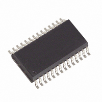
DS8313-RRX+ Maxim Integrated Products, DS8313-RRX+ Datasheet - Page 14

DS8313-RRX+
Manufacturer Part Number
DS8313-RRX+
Description
IC INTERFACE SMART CARD 28-SOIC
Manufacturer
Maxim Integrated Products
Type
Smart Card Interface ICr
Specifications of DS8313-RRX+
Applications
Smart Card
Interface
Analog
Voltage - Supply
2.7 V ~ 6 V
Package / Case
28-SOIC (7.5mm Width)
Mounting Type
Surface Mount
Operating Supply Voltage
2.7 V to 6 V
Supply Current
0.75 mA to 80.75 mA
Maximum Operating Temperature
+ 85 C
Minimum Operating Temperature
- 40 C
Mounting Style
SMD/SMT
Lead Free Status / RoHS Status
Lead free / RoHS Compliant
Smart Card Interface
A low-power state, stop mode, can be entered by forc-
ing the CMDVCC, 5V/3V, and 1_8V input pins to a
logic-high state. Stop mode can only be entered when
the smart card interface is inactive. In stop mode all
internal analog circuits are disabled. The OFF pin fol-
lows the status of the PRES pin. To exit stop mode,
change the state of one or more of the three control
Figure 8. Stop-Mode Sequence
14
______________________________________________________________________________________
STOP MODE
Stop Mode (Low-Power Mode)
CMDVCC
5V/3V
1_8V
PRES
VCC
OFF
DEACTIVATE INTERFACE
PRES IN STOP MODE
OFF FOLLOWS
STOP MODE
ACTIVATE
pins to a logic-low. An internal 220µs (typ) power-up
delay and the 8ms PRES debounce delay are in effect
and OFF is asserted to allow the internal circuitry to sta-
bilize. This prevents smart card access from occurring
after leaving the stop mode. Figure 8 shows the control
sequence for entering and exiting stop mode. Note that
an in-progress deactivation sequence always finishes
before the DS8113 enters low-power stop mode.
220μs DELAY
DEACTIVATE
STOP MODE
OFF ASSERTED TO
WAIT FOR DELAY
8ms DEBOUNCE


