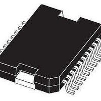
LNBK20PD-TR STMicroelectronics, LNBK20PD-TR Datasheet - Page 6

LNBK20PD-TR
Manufacturer Part Number
LNBK20PD-TR
Description
IC LNB SUPPLY & CNTRL 20-PWRSOIC
Manufacturer
STMicroelectronics
Datasheet
1.LNBK20PD.pdf
(25 pages)
Specifications of LNBK20PD-TR
Interface
Parallel
Voltage - Supply
15 V ~ 27 V
Package / Case
PowerSO-20 Exposed Bottom Pad
Mounting Type
Surface Mount
Polarity
Positive
Number Of Outputs
2
Output Type
Selectable
Output Voltage
13 V, 18 V
Line Regulation
50 mV
Load Regulation
150 mV
Input Voltage Max
28 V
Maximum Operating Temperature
+ 125 C
Minimum Operating Temperature
- 40 C
Maximum Power Dissipation
14000 mW
Mounting Style
SMD/SMT
Lead Free Status / RoHS Status
Lead free / RoHS Compliant
Applications
-
Lead Free Status / Rohs Status
Lead free / RoHS Compliant
Available stocks
Company
Part Number
Manufacturer
Quantity
Price
Pin configuration
Table 2.
6/25
5, 6, 15,
PIN N°
7, 13
16
10
11
12
14
18
19
20
1
2
3
4
8
9
Pin description for SO-20
SYMBOL
EXTM
LNBB
LNBA
OSEL
CEXT
GND
V
V
V
N.C.
ENT
OLF
LLC
EN
MI
CC1
CC2
SEL
Output Voltage Selection:
Line Length Compens.
22KHz Tone Enable
External Modulator
External Capacitor
Over Load Flag
Not Connected
13 or 18V (typ)
Supply Input 1
Supply Input 2
Port Selection
Master Input
Port Enable
Output Port
Output Port
(1V typ)
Ground
NAME
Logic control input: see truth table
Logic output (open collector). Normally in HIGH
IMPEDANCE, goes LOW when current or thermal
overload occurs
In stand-by mode, the voltage on MI is routed to LNBA pin.
Can be left open if bypass function is not needed
See truth tables for voltage and port selection
Circuit Ground. It is internally connected to the die frame
15V to 27V supply. It is automatically selected when
V
22V to 27V supply. It is automatically selected when
V
See truth table voltage and port selection. In stand-by
mode this port is powered by the MI pin via the internal
Bypass Switch
Logic control input: see truth table
Logic control input: see truth table
Logic control input: see truth table
Logic control input: see truth table
Timing Capacitor used by the Dynamic Overload
protection. Typical application is 4.7µF for a 1200ms cycle
External Modulation Input. Needs DC decoupling to the
AC source. if not used, can be left open.
OUT
OUT
= 13 or 14V
= 18 or 19V
FUNCTION
LNBK20


