VHB75W-Q24-S15 CUI Inc, VHB75W-Q24-S15 Datasheet - Page 5
VHB75W-Q24-S15
Manufacturer Part Number
VHB75W-Q24-S15
Description
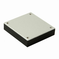
CONVERTER DC/DC 75W 15V 5A
Manufacturer
CUI Inc
Series
V-Infinity VHB75Wr
Type
With Remote On/Off and UVLOr
Datasheet
1.VHB75W-Q24-S15.pdf
(10 pages)
Specifications of VHB75W-Q24-S15
Voltage - Input (min)
9V
Voltage - Input (max)
36V
Number Of Outputs
1
Power (watts) - Manufacture Series
75W
Power (watts) - Max
75W
1st Output
15 VDC @ 5A
2nd Output
-
3rd Output
-
Voltage - Isolation
1.5kV (1500V)
Mounting Type
Through Hole
Package / Case
9-DIP Module, 1/2 Brick
Size / Dimension
2.40" L x 2.28" W x 0.50" H (61mm x 57.9mm x 12.7mm)
Operating Temperature
-40°C ~ 100°C
Efficiency
84%
Lead Free Status / Rohs Status
Lead free / RoHS Compliant
Other names
102-2251
VHB75W-Q24-S15
VHB75W-Q24-S15


PART NUMBER: VHB75W
2. INPUT VOLTAGE RANGE
It is important to ensure the input voltage measured at the converter input pins is within the range for that converter. Make sure wire
losses and voltage ripples are accounted for. One possible problem is driving the converter with a linear unregulated power supply.
For example, if the average voltage measured by a DMM is 9V, with a voltage ripple of 3Vpp, the actual input can swing from 7.5V to
10.5V. This will be outside the specified input range of 9-36V and the converter may not function properly. On the other end, make
sure the actual input voltage does not exceed the highest voltage of 36V or 75V.
3. LEAD WIRES
Make sure the input and output wires are of adequate AWG size to minimize voltage drop, and ensure the voltage across the input
terminals is above the converter's rated minimum voltage at all times. It is recommended to have the wire pairs twisted, respectively
for the input pair and the output pair, so as to minimize noise pickup.
4. INPUT CURRENT
The input voltage source must be able to provide enough current to the converter, otherwise it may not start up or operate properly. A
typical symptom is not starting or unusually low output voltage. In general, it is recommended to be able to provide at least:
Ipeak = 150%*Pout/(η η *Vmin) where Pout is the maximum output power, Vmin is the minimum input voltage and η is the converter's
efficiency. As an example, for VHB75W-Q24-S5 to operate with 9~36 V input, 75 W output and an efficiency of 82%, the minimum
source current is recommended to be: Ipeak = 150% * 75 / (82% * 9) = 15.24 A.
5. INPUT FUSE
To limit the input current and to facilitate input reversal protection and input OVP protection, a fast-acting input fuse is recommended
for the input line. The fuse rating will depend on the input range and should allow for the maximum current at the lowest input volt-
age, as shown in this equation: Ipeak = 150%*Pout/(η η *Vmin).
In the previous example of VHB75W-Q24-S5, the peak input current at 9V was calculated to be 15.24 A. A 20 A fuse may be suitable
for this application. Make sure the fuse voltage rating is higher than the maximum input voltage.
6. REMOTE SENSE
The converter provides regulated outputs at the output terminals. When there is a large current and/or the output cable is of some
length, the voltage at the end of the output cable may be noticeably lower than at the terminals. The converter can compensate up to
0.5V of voltage drop through remote sense terminals. To ensure accurate regulation, run two separate wires (twisted) from the
desired regulation points to the remote sense terminals, as shown below. Even if the load current is low, still connect +Vo to +S and
-Vo to -S.
20050 SW 112
th
Ave. Tualatin, Oregon 97062
Trim
+Vo
-Vo
+S
-S
FIGURE 2. REMOTE SENSE
phone
phone 503.612.2300 fax
DESCRIPTION: half-brick dc-dc converter
fax 503.612.2383
(+)
(-)
Load
www.v-infinity.com
page
date
04/2011
5 of 10
Related parts for VHB75W-Q24-S15
Image
Part Number
Description
Manufacturer
Datasheet
Request
R

Part Number:
Description:
CONVERTER DC/DC 75W 24V 3.12A
Manufacturer:
CUI Inc
Datasheet:
Part Number:
Description:
CONVERTER DC/DC 75W 15V 5A
Manufacturer:
CUI Inc
Datasheet:
Part Number:
Description:
CONVERTER DC/DC 75W 24V 3.12A
Manufacturer:
CUI Inc
Datasheet:
Part Number:
Description:
CONVERTER DC/DC 75W 5V 15A
Manufacturer:
CUI Inc
Datasheet:
Part Number:
Description:
CONVERTER DC/DC 75W 12V 6.25A
Manufacturer:
CUI Inc
Datasheet:
Part Number:
Description:
CONVERTER DC/DC 75W 12V 6.25A
Manufacturer:
CUI Inc
Datasheet:
Part Number:
Description:
CONVERTER DC/DC 75W 48V 1.56A
Manufacturer:
CUI Inc
Datasheet:
Part Number:
Description:
CONVERTER DC/DC 75W 48V 1.56A
Manufacturer:
CUI Inc
Datasheet:

Part Number:
Description:
LINE DRIVER CABLE FOR AMT-102 1M
Manufacturer:
CUI Inc
Datasheet:

Part Number:
Description:
LINE DRIVER CABLE FOR AMT-103 1M
Manufacturer:
CUI Inc
Datasheet:

Part Number:
Description:
SPEAKER ALNICO 8OHM 2W 100MM SQR
Manufacturer:
CUI Inc
Datasheet:

Part Number:
Description:
ac-dc converter
Manufacturer:
CUI [CUI INC]
Datasheet:
Part Number:
Description:
MEDICAL SWITCHING POWER SUPPLY
Manufacturer:
CUI [CUI INC]
Datasheet:
Part Number:
Description:
DC-DC Converter
Manufacturer:
CUI [CUI INC]
Datasheet:
Part Number:
Description:
DC/DC Converter
Manufacturer:
CUI [CUI INC]
Datasheet: