XCARD XC-1 XMOS, XCARD XC-1 Datasheet - Page 3
XCARD XC-1
Manufacturer Part Number
XCARD XC-1
Description
BOARD DEV KIT XS1-G4
Manufacturer
XMOS
Series
XCore™r
Type
MCUr
Datasheets
1.XS1-G04B-FB144-C4.pdf
(22 pages)
2.XCARD_XC-1.pdf
(2 pages)
3.XCARD_XC-1.pdf
(21 pages)
4.XCARD_XC-1.pdf
(17 pages)
Specifications of XCARD XC-1
Contents
Board, Cable
Lead Free Status / Rohs Status
Lead free / RoHS Compliant
For Use With/related Products
XS1-G4
Other names
880-1013


XC-1 Hardware Manual (1.3.2)
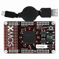
The XC-1 provides a single four core XS1-G4 device in a 512BGA package. Each
XCore is programmable and comprises an event-driven multi-threaded processor
with tightly integrated general purpose I/O pins and 64 KBytes of on-chip RAM. The
The processors have ports that are directly connected to the I/O pins. Examples of
The XC-1 has 16 user-configurable LEDs. Four of green LEDs are positioned next
2 XS1-G4 Device [A]
pins on XCore0 and XCore2 are brought out of the package and connected to the
card’s components as follows:
Processor 0
Processor 2
how to write software that interfaces over these ports with the XC-1 components is
provided in a separate tutorial [1].
3 User-configurable LEDs [B and C]
to the four push-buttons (collectively referred to as button-LEDs) and contain green
diodes. The other 12 LEDs are positioned around the XS1-G4 in a circle (collectively
referred to as clock-LEDs) and contain red/green diodes. A Roman numeral is printed
next to each LED. Each of the LEDs can be driven by software. The layout of the LEDs
is shown on the following page.
Twelve red/green and four green LEDs
Four push-button switches
Speaker
Three 16-way I/O expansion headers (24 I/O bits)
One 16-way I/O expansion headers (16 I/O bits)
www.xmos.com
3/17
Related parts for XCARD XC-1
Image
Part Number
Description
Manufacturer
Datasheet
Request
R

Part Number:
Description:
BOARD DEV KIT XS1-G4 ETHERNET
Manufacturer:
XMOS
Datasheet:

Part Number:
Description:
BOARD DEV KIT XS1-G4
Manufacturer:
XMOS
Datasheet:

Part Number:
Description:
DEV KIT EVENT-DRIVEN PROC XS1-L1
Manufacturer:
XMOS
Datasheet:

Part Number:
Description:
BOARD KIT XS1-G4 LED CTRL TILE
Manufacturer:
XMOS
Datasheet:

Part Number:
Description:
ADAPTER USB DEBUGGER JTAG XSYS2
Manufacturer:
XMOS
Datasheet:

Part Number:
Description:
IC MPU 32BIT SINGLE CORE 64LQFP
Manufacturer:
XMOS
Datasheet:

Part Number:
Description:
IC MPU 32BIT SINGLE CORE 64LQFP
Manufacturer:
XMOS
Datasheet:
Part Number:
Description:
IC MPU 32BIT SINGLE CORE 64LQFP
Manufacturer:
XMOS
Datasheet:

Part Number:
Description:
IC MPU 32BIT SINGLE CORE 64LQFP
Manufacturer:
XMOS
Datasheet:
Part Number:
Description:
IC MPU 32BIT SINGLE CORE 64LQFP
Manufacturer:
XMOS
Datasheet:

Part Number:
Description:
IC MPU 32BIT SINGLE CORE 128TQFP
Manufacturer:
XMOS
Datasheet:
Part Number:
Description:
IC MPU 32BIT SINGLE CORE 64LQFP
Manufacturer:
XMOS
Datasheet:
Part Number:
Description:
IC MPU 32BIT SINGLE CORE 128TQFP
Manufacturer:
XMOS
Datasheet:
Part Number:
Description:
IC MPU 32BIT SINGLE CORE 128TQFP
Manufacturer:
XMOS
Datasheet:

Part Number:
Description:
IC MPU 32BIT DUAL CORE 124QFN
Manufacturer:
XMOS
Datasheet: