CB-OWS451I-04-0 ConnectBlue, CB-OWS451I-04-0 Datasheet - Page 17
CB-OWS451I-04-0
Manufacturer Part Number
CB-OWS451I-04-0
Description
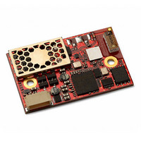
RF SERIAL PORT ADAPTER INT ANT
Manufacturer
ConnectBlue
Series
CB-OWSr
Specifications of CB-OWS451I-04-0
Frequency
2.4GHz, 5GHz
Data Rate - Maximum
115 kbps
Modulation Or Protocol
802.11 a/b/g/n
Applications
General Purpose
Power - Output
20dBm (100mW)
Sensitivity
-89dBm
Voltage - Supply
3.3 V ~ 5.5 V
Current - Receiving
-
Current - Transmitting
-
Data Interface
Solder Pad
Memory Size
-
Antenna Connector
On-Board, Chip
Operating Temperature
-40°C ~ 85°C
Package / Case
Modular
Lead Free Status / Rohs Status
Lead free / RoHS Compliant
Other names
809-1042


connectBlue
Copyright © 2010 connectBlue AB
Unable to render embedded object: File (w23_measure_A.PNG) not found.
Antenna keep out area 10.2mm x 6.9mm. No copper inside this area.
Tolerances:
Unable to render embedded object: File (w23_measure_B.PNG) not found.
Unable to render embedded object: File (w23_measure_C.PNG) not found.
There are 2 x 2.3mm mounting holes on cB-0942. The reasons for the 2.3mm holes are that the threaded M2 holes on the single and
double row connectors (see section 4.2.1) are not aligned. The outer tangents of the 2.3mm holes align the module if the single row
connectors are used and the inner if double row connectors are used (see Figure 11).
Choose the outer tangent (CC distance 27.24mm) if the module is aligned and mounted with some other technique based on M2 screws
(e.g. press-fit nuts), see Figure 12.
The board-to-board connector should be a 1 mm pitch one-piece part connector. The recommended manufacture is Samtec with many
connector options available; see section 4.2.1.1.
Chapter 2 contains more information about the connector and the electrical interface.
This connector is a double row connector and connects both J2 and J3. It connector has a height of 3.0 mm and this has to be
considered if components are to be mounted on the motherboard under the board. The connector is also available with a height of 6.0
mm and 10.0 mm (The FSI-120 serie from Samtec).
There are alignment pins on the bottom side of the connector.
The connector is available with M2 threaded inserts (ASP-118580-01) that fit the mounting holes on the board. You may screw the board
directly into these inserts. If you want to have a tighter and more secure mounting you may use longer screws and secure it using a nut
on the backside of the motherboard.
Another way to mount the module is to use press-fit nuts on the motherboard and skip the M2 threads on the connector
(ASP-118581-01), see section 4.3 for more information about press-fit nuts.
5 Mounting information
5.1 Module dimensions
5.2 Using the J2/J3 board-to-board connectors
Samtec order
number
REF-120021-01
REF-120021-02
REF-120018-01
5.1.1 Mounting holes
5.2.1 Suitable one-piece part connectors
5.2.2 Double row ASP-118580-01 / ASP-118581-01 connectors
1.
2.
Outline dimensions +/- 0.1mm
Drilled hole to outline: +/- 0.05mm
Quote
number
55392
55392
55392
Equivalent part
FSI-120-03-G-D-AB
FSI-120-03-G-D-AB-K-TR
FSI-120-03-G-D-M-AB
Package
Tube
Tape-n-Reel Align pin on bottom side only
Tube
Remark
Align pin on bottom side only
With M2 threaded inserts and align pin on bottom
side only
Page 17 of 26
Related parts for CB-OWS451I-04-0
Image
Part Number
Description
Manufacturer
Datasheet
Request
R

Part Number:
Description:
RF SERIAL PORT ADAPTER U.FL
Manufacturer:
ConnectBlue
Datasheet:

Part Number:
Description:
KIT ACCY BLUETOOTH/WLAN RS232
Manufacturer:
ConnectBlue
Datasheet:
Part Number:
Description:
KIT ACCY BLUETOOTH/WLAN USB SPA
Manufacturer:
ConnectBlue
Datasheet:


Part Number:
Description:
KIT STARTER OEM SRL 311I RS232
Manufacturer:
ConnectBlue
Datasheet:

Part Number:
Description:
KIT START OEM WIRELESS LAN RS232
Manufacturer:
ConnectBlue
Datasheet:

Part Number:
Description:
KIT DEV BLUETOOTH I/O 311I
Manufacturer:
ConnectBlue
Datasheet:

Part Number:
Description:
KIT STARTER OEM SERIAL 311I USB
Manufacturer:
ConnectBlue
Datasheet:

Part Number:
Description:
CB-1011B-79=TIME DELAY REL
Manufacturer:
Tyco Electronics
Datasheet:
Part Number:
Description:
CB-1014B-79=TIME DELAY REL
Manufacturer:
Tyco Electronics
Datasheet:

Part Number:
Description:
Standard Clock Oscillators 100MHz 50ppm 3.3Volt -40 to 85C
Manufacturer:
TXC Corporation
Datasheet:
Part Number:
Description:
Standard Clock Oscillators 133.33MHz 50ppm 3.3Volt -40 to 85C
Manufacturer:
TXC Corporation
Datasheet: