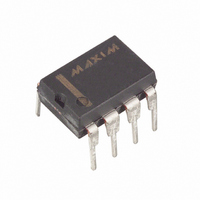
MAX4544CPA+ Maxim Integrated Products, MAX4544CPA+ Datasheet - Page 6

MAX4544CPA+
Manufacturer Part Number
MAX4544CPA+
Description
IC SWITCH SPDT 8DIP
Manufacturer
Maxim Integrated Products
Datasheet
1.MAX4544EUTT.pdf
(16 pages)
Specifications of MAX4544CPA+
Function
Switch
Circuit
1 x SPDT
On-state Resistance
60 Ohm
Voltage Supply Source
Single Supply
Voltage - Supply, Single/dual (±)
2.7 V ~ 12 V
Operating Temperature
0°C ~ 70°C
Mounting Type
Through Hole
Package / Case
8-DIP (0.300", 7.62mm)
Number Of Switches
1
Switch Configuration
SPDT
On Resistance (max)
60 Ohms
On Time (max)
100 ns
Off Time (max)
75 ns
Off Isolation (typ)
- 76 dB
Supply Voltage (max)
12 V
Supply Voltage (min)
2.7 V
Maximum Power Dissipation
727 mW
Maximum Operating Temperature
+ 70 C
Mounting Style
Through Hole
Description/function
Analog Switch
Input Level
CMOS, TTL
Minimum Operating Temperature
0 C
Off State Leakage Current (max)
5 nA
Lead Free Status / RoHS Status
Lead free / RoHS Compliant
Low-Voltage, Single-Supply
Dual SPST/SPDT Analog Switches
Figure 1. Overvoltage Protection Using Two External Blocking
Diodes
6
DIP/SO/
µMAX/
TDFN
EP
—
—
—
—
—
—
—
_______________________________________________________________________________________
1
2
3
4
5
6
7
8
MAX4541
SOT23-8
V g
—
—
—
—
—
—
—
—
1
8
3
6
5
4
7
2
Applications Information
DIP/SO/
µMAX/
TDFN
NO
EP
—
—
—
—
—
—
—
2
3
4
6
7
8
1
5
POSITIVE SUPPLY
MAX4542
GND
V+
SOT23-8
D1
D2
—
—
—
—
—
—
—
—
8
3
6
4
7
2
1
5
COM
PIN
DIP/SO/
µMAX/
TDFN
EP
—
—
—
—
—
—
—
1
2
3
4
6
7
8
5
MAX4543
SOT23-8
—
—
—
—
—
—
—
—
1
8
3
6
4
7
2
5
DIP/SO/
µMAX/
TDFN
5, 6
EP
—
—
—
—
—
—
—
—
4
8
1
2
3
7
The MAX4541–MAX4544 are TTL compatible when
powered from a single +5V supply. When powered
from other supply voltages, TTL compatibility is guar-
anteed and the logic inputs can be driven rail-to-rail.
For example, with a +12V supply, IN1 and IN2 can be
driven low to 0 and high to 12V. With a +3.3V supply,
IN1 and IN2 should be driven low to 0 and high to
3.3V.
Driving IN1 and IN2 rail-to-rail minimizes power con-
sumption.
Analog signals that range over the entire supply voltage
(V+ to GND) can be switched with very little change in
on-resistance over the entire voltage range (see the
Typical Operating Characteristics). All the switches are
bidirectional, so the NO_, NC_, and COM_ pins can be
used as either inputs or outputs.
MAX4544
SOT23-6
—
—
—
—
—
—
—
—
—
—
3
2
6
5
4
1
NAME
NAME
COM1
COM2
COM
GND
NO2
NC1
NC2
N.C.
NO1
IN2
IN1
NO
NC
V+
EP
IN
Analog Switch 1—Normally Open
Analog Switch 1—Common
Digital Control Input 2
Ground—Negative Supply Input
Analog Switch 2—Normally Open
Analog Switch 2—Common
Digital Control Input 1
Positive Supply Voltage Input
Analog Switch 1—Normally Closed
Analog Switch 2—Normally Closed
Analog Switch—Normally Open
Analog Switch—Common
Analog Switch—Normally Closed
Not Connected (Open Circuit)
Digital Control Input
Exposed Pad. Connect EP to V+.
Analog Signal Levels
Pin Description
FUNCTION
Logic Levels


