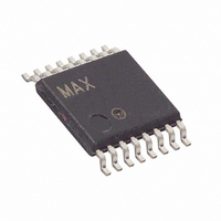
MAX14752EUE+ Maxim Integrated Products, MAX14752EUE+ Datasheet - Page 12

MAX14752EUE+
Manufacturer Part Number
MAX14752EUE+
Description
IC MULTIPLEXER 8X1 16TSSOP
Manufacturer
Maxim Integrated Products
Type
Analog Multiplexerr
Datasheet
1.MAX14752EUE.pdf
(15 pages)
Specifications of MAX14752EUE+
Function
Multiplexer
Circuit
1 x 8:1
On-state Resistance
130 Ohm
Voltage Supply Source
Single, Dual Supply
Voltage - Supply, Single/dual (±)
20 V ~ 72 V, ±10 V ~ 36 V
Operating Temperature
-40°C ~ 85°C
Mounting Type
Surface Mount
Package / Case
16-TSSOP
Product
Multiplexer
Number Of Lines (input / Output)
8.0 / 1.0
Supply Voltage (max)
36 V
Supply Voltage (min)
10 V
Maximum Operating Temperature
+ 85 C
Minimum Operating Temperature
- 40 C
Mounting Style
SMD/SMT
Number Of Input Lines
8.0
Number Of Output Lines
1.0
Power Dissipation
890 mW
Package
16TSSOP
Maximum On Resistance
60@±35V Ohm
Maximum Propagation Delay Bus To Bus
10000(Typ)@±35V ns
Maximum High Level Output Current
100 mA
Multiplexer Architecture
8:1
Maximum Turn-off Time
800(Typ)@±35V ns
Maximum Turn-on Time
1000(Typ)@±35V ns
Power Supply Type
Single|Dual
Lead Free Status / RoHS Status
Lead free / RoHS Compliant
8-Channel/Dual 4-Channel
72V Analog Multiplexers
12
PIN
PIN
10
11
12
13
14
15
16
10
11
12
13
14
15
16
1
2
3
4
5
6
7
8
9
1
2
3
4
5
6
7
8
9
______________________________________________________________________________________
NAME
NAME
OUTA
OUTB
GND
INA0
INA1
INA2
INA3
INB3
INB2
INB1
INB0
GND
OUT
V
V
V
V
IN0
IN1
IN2
IN3
IN7
IN6
IN5
IN4
EN
EN
S0
S2
S1
S0
S1
DD
DD
SS
SS
Mux Input Select
Mux Enable. Drive EN high to enable the device. The EN high voltage defines input logic voltage level for
S0, S1, and S2.
Negative Supply Voltage. Bypass V
Bidirectional Analog Input
Bidirectional Analog Input
Bidirectional Analog Input
Bidirectional Analog Input
Bidirectional Analog Output
Bidirectional Analog Input
Bidirectional Analog Input
Bidirectional Analog Input
Bidirectional Analog Input
Positive Supply Voltage. Bypass V
Ground. Connect GND to V
supply.
Mux Input Select
Mux Input Select
Mux Input Select
Mux Enable. Drive EN high to enable the device. The EN high voltage defines input logic voltage level for
S0 and S1.
Negative Supply Voltage. Bypass V
Bidirectional Analog Input
Bidirectional Analog Input
Bidirectional Analog Input
Bidirectional Analog Input
Bidirectional Analog Output
Bidirectional Analog Output
Bidirectional Analog Input
Bidirectional Analog Input
Bidirectional Analog Input
Bidirectional Analog Input
Positive Supply Voltage. Bypass V
Ground. Connect GND to V
supply.
Mux Input Select
MAX14752 Pin Description (Single 8-to-1 Mux)
SS
SS
MAX14753 Pin Description (Dual 4-to-1 Mux)
for single supply. Bypass GND to V
for single supply. Bypass GND to V
DD
DD
SS
SS
to GND with a 1µF ceramic capacitor.
to GND with a 1µF ceramic capacitor.
to GND with a 1µF ceramic capacitor.
to GND with a 1µF ceramic capacitor.
FUNCTION
FUNCTION
SS
SS
with a 1µF ceramic capacitor for dual
with a 1µF ceramic capacitor for dual


