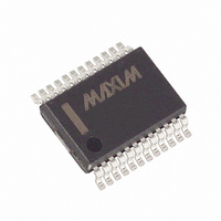
MAX395CAG+ Maxim Integrated Products, MAX395CAG+ Datasheet - Page 13

MAX395CAG+
Manufacturer Part Number
MAX395CAG+
Description
IC SWITCH OCTAL SPST 24SSOP
Manufacturer
Maxim Integrated Products
Datasheet
1.MAX395EWG.pdf
(16 pages)
Specifications of MAX395CAG+
Function
Switch
Circuit
8 x SPST - NO
On-state Resistance
175 Ohm
Voltage Supply Source
Single, Dual Supply
Voltage - Supply, Single/dual (±)
2.7 V ~ 16 V, ±2.7 V ~ 8 V
Current - Supply
7µA
Operating Temperature
0°C ~ 70°C
Mounting Type
Surface Mount
Package / Case
24-SSOP
Switch Configuration
SPST
On Resistance (max)
125 Ohms
On Time (max)
500 ns
Off Time (max)
500 ns
Off Isolation (typ)
- 90 dB
Supply Voltage (max)
8 V
Supply Voltage (min)
3 V
Supply Current
30 uA
Maximum Power Dissipation
1000 mW
Maximum Operating Temperature
+ 70 C
Mounting Style
Through Hole
Minimum Operating Temperature
0 C
Off State Leakage Current (max)
10 nA
Lead Free Status / RoHS Status
Lead free / RoHS Compliant
To use the MAX395 as an 8x1 multiplexer, connect all
common pins together (COM0–COM7) to form the mux
output; the mux inputs are NO0–NO7.
The mux can be programmed normally, with only one
channel selected for every eight clock pulses, or it can
be programmed in a fast mode, where channel chang-
ing occurs on each clock pulse. In this mode, the chan-
nels are selected by sending a single high pulse
(corresponding to the selected channel) at DIN, and a
corresponding CS low pulse for every eight clock puls-
es. As this is clocked through the register by SCLK,
each switch sequences one channel at a time, starting
with Channel 7.
Figure 3. Connections for Microwire
Figure 5. Daisy-Chained Connection
THE DOUT-SI CONNECTION IS NOT REQUIRED FOR WRITING TO THE
MAX395, BUT MAY BE USED FOR DATA-ECHO PURPOSES.
SCLK
DIN
CS
MAX395
DOUT
SCLK
______________________________________________________________________________________
DIN
CS
SCLK
DIN
CS
MAX395
SK
SO
SI
I/O
DOUT
8x1 Multiplexer
Serially Controlled, Low-Voltage,
MICROWIRE
PORT
SCLK
DIN
CS
MAX395
8-Channel SPST Switch
DOUT
To use the MAX395 as a dual (4x2) mux, connect
COM0–COM3 together and connect COM4–COM7
together, forming the two outputs. The mux input pairs
become NO0/NO4, NO1/NO5, NO2/NO6, and NO3/NO7.
The mux can be programmed normally, with only one
differential channel selected for every eight clock puls-
es, or it can be programmed in a fast mode, where
channel changing occurs on each clock pulse.
In fast mode, the channels are selected by sending two
high pulses spaced four clock pulses apart (corre-
sponding to the two selected channels) at DIN, and a
corresponding CS low pulse for each of the first eight
clock pulses. As this is clocked through the register by
Figure 4. Connections for SPI and QSPI
Dual, Differential 4-Channel Multiplexer
THE DOUT-MISO CONNECTION IS NOT REQUIRED FOR WRITING TO THE
MAX395, BUT MAY BE USED FOR DATA-ECHO PURPOSES.
MAX395
SCLK
DIN
CS
DOUT
SCLK
MAX395
DIN
CS
DOUT
CPOL = 0, CPHA = 0
MISO
MOSI
SCK
I/O
TO OTHER
SERIAL DEVICES
PORT
SPI
13


