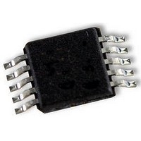
LV8548M-TLM-H ON Semiconductor, LV8548M-TLM-H Datasheet - Page 4

LV8548M-TLM-H
Manufacturer Part Number
LV8548M-TLM-H
Description
2-CH BRUSH MOTOR DRIVER
Manufacturer
ON Semiconductor
Datasheet
1.LV8548M-TLM-H.pdf
(6 pages)
Specifications of LV8548M-TLM-H
Motor Type
Stepper
No. Of Outputs
2
Output Current
1A
Supply Voltage Range
4V To 16V
No. Of Pins
10
Operating Temperature Range
-30°C To +85°C
Svhc
No SVHC (20-Jun-2011)
Rohs Compliant
Yes
Lead Free Status / Rohs Status
Supplier Unconfirmed
Pin function
Operation explanation
1. DCM output control logic
Pin No.
IN1
H
H
L
L
L
10
1
2
3
4
5
6
7
8
9
IN2
H
H
L
L
L
V CC
IN1
IN2
IN3
IN4
GND
OUT4
OUT3
OUT2
OUT1
Input
Pin name
IN3
H
H
L
L
L
IN4
H
H
L
L
L
Power-supply voltage pin.
V CC voltage is impressed. The permissible operation voltage is from
4.0 to 16.0(V). The capacitor is connected for stabilization for GND pin
(6pin).
Motor drive control input pin.
Driving control input pin of OUT1 (10pin) and OUT2 (9pin). It combines
with IN2 pin (3pin) and it fights desperately. The digital input it, range of
the "L" level input is 0 to 0.7(V), range of the "H" level input is from 1.8 to
5.5(V). PWM can be input. Pull-down resistance 100(kΩ) is built into in
the pin. It becomes a standby mode because all IN1, IN2, IN3, and IN4
pins are made "L", and the circuit current can be adjusted to 0.
Motor drive control input pin.
Driving control input pin of OUT1 (10pin) and OUT2 (9pin). It combines
with IN1 pin (2pin) and it uses it. PWM can be input. With built-in
pull-down resistance.
Motor drive control input pin.
Driving control input pin of OUT3 (8pin) and OUT4 (7pin). It combines
with IN4 pin (5pin) and it uses it. PWM can be input. With built-in
pull-down resistance.
Motor drive control input pin.
Driving control input pin of OUT3 (8pin) and OUT4 (7pin). It combines
with IN3 pin (4pin) and it uses it. PWM can be input. With built-in
pull-down resistance.
Ground pin.
Driving output pin.
The motor coil is connected between terminal OUT3 (8pin).
Driving output pin.
The motor coil is connected between terminal OUT4 (7pin).
Driving output pin.
The motor coil is connected between terminal OUT1 (10pin).
Driving output pin.
The motor coil is connected between terminal OUT2 (9pin).
OUT1
OFF
OFF
H
L
L
OUT2
OFF
OFF
H
L
L
Output
Pin function
OUT3
OFF
OFF
H
L
L
LV8548M
OUT4
OFF
OFF
H
L
L
1CH
2CH
Remarks
Stand-by
Stand-by
Stand-by
Reverse
Reverse
Forward
Forward
Brake
Brake
(OUT3)
OUT1
Equivalent Circuit
V CC
No.A1802-4/6
(OUT4)
OUT2


