BF240A01BK1200 APEM Components, BF240A01BK1200 Datasheet - Page 3
BF240A01BK1200
Manufacturer Part Number
BF240A01BK1200
Description
83R9412
Manufacturer
APEM Components
Datasheet
1.BF240A01BK1200.pdf
(8 pages)
Specifications of BF240A01BK1200
No. Of Axes
1
Supply Voltage Max
5V
Centre Voltage
2V
Switch Terminals
Connector
Handle Style
Paddle Thumbwheel
Svhc
No SVHC (20-Jun-2011)
Handle Type1
Paddle Thumbwheel
Rohs Compliant
Yes


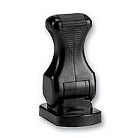
BF SERIES PADDLE - CONTACTLESS JOYSTICK & SWITCH
CONFIGURATIONS & OUTPUTS
OUTPUT OPTIONS
The BF Series Paddle is configured as two “electrical” controls in one mechanical package. The Paddle operates from 5V and
provides two proportional outputs. The second output is accurate to the first within +/-2% of the power supply. The power supply
for the secondary output is also completely independent. Customers may choose their preference of voltage outputs (gains).
The secondary output can be of the same or inverse polarity to the primary wiper. For example, with a secondary inverse output,
the first and second outputs can be summed and compared to zero to verify that the joystick is operating correctly. Paddles having
two identical outputs of the same polarity may be used to drive two identical dual redundant circuits.
There are also two Hall Effect switches that trigger at pre-determined lever positions.
The BF Series Paddle may be specified with a variety of PWM output options. For more details on available PWM options please
refer to Apem.
ADDITIONAL OUTPUT INFORMATION
SELECTABLE SWITCHING POINTS
The Paddle incorporates two Hall Effect switches. The angle of the lever at the switch trigger point can be selected when ordering.
If no switches are specified then the output on pins 2 and 7 will be unused.
The outputs are configured as ‘open drain’ type with a 1K5 pull up resistor to 5V.
GAIN OPTIONS
The voltage output on the wiper, at full scale deflection is determined by the gain. The gain is expressed as a percentage of the
voltage supplied. Therefore (assuming a 5V supply) a Paddle specified with +/- 25% gain would yield 1.25V at South, 2.5V at
centre and 3.75V at North. A range of gain options are available as standard. All controls are supplied pre-set and no further
calibration is needed throughout the lifetime of operation.
OUTPUT IMPEDANCE
The voltage outputs at centre and at each end of travel are specified across an infinite load, with no current flowing. The output
impedance specified in the electrical specification should be taken into account when designing a system. Load resistance of less
than 10K Ohms is not recommended.
www.apem.com
3
Note: The company reserves the right to change specifications without notice.
Related parts for BF240A01BK1200
Image
Part Number
Description
Manufacturer
Datasheet
Request
R

Part Number:
Description:
SWITCH OPERATOR ROUN 1 OR 2 POLE
Manufacturer:
APEM Components
Datasheet:

Part Number:
Description:
SWITCH OPERATOR SQ 1 OR 2 POL
Manufacturer:
APEM Components
Datasheet:

Part Number:
Description:
SWITCH OPERATOR KEYLOCK ROUND
Manufacturer:
APEM Components
Datasheet:

Part Number:
Description:
SWITCH OPERATOR RECT 1 OR 2 POLE
Manufacturer:
APEM Components
Datasheet:
Part Number:
Description:
SWITCH OPERATOR KEYLOCK ROUND
Manufacturer:
APEM Components
Datasheet:
Part Number:
Description:
SWITCH OPERATOR KEYLOCK ROUND
Manufacturer:
APEM Components
Datasheet:

Part Number:
Description:
SWITCH OPERATOR SQ 3 OR 4 POLE
Manufacturer:
APEM Components
Datasheet:

Part Number:
Description:
INDICATOR 12V 14MM PROMINENT GRN
Manufacturer:
APEM Components
Datasheet:

Part Number:
Description:
SWITCH HARDWARE
Manufacturer:
APEM Components
Datasheet:
Part Number:
Description:
STANDARD SLIDE SWITCH
Manufacturer:
APEM Components
Datasheet:

Part Number:
Description:
SWITCH TOGGLE SPDT ON-ON SLDR
Manufacturer:
APEM Components
Datasheet: