1D1-5F-15-71 APEM Components, 1D1-5F-15-71 Datasheet - Page 5
1D1-5F-15-71
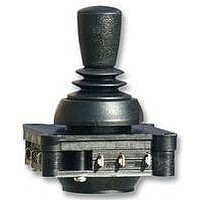
Manufacturer Part Number
1D1-5F-15-71
Description
59M4253
Manufacturer
APEM Components
Datasheet
1.1D1-5F-15-71.pdf
(6 pages)
Specifications of 1D1-5F-15-71
Contact Configuration
SPST-CO
No. Of Axes
2
Contact Voltage Ac Max
250V
Contact Current Ac Max
6A
Switch Terminals
Solder
Lever Travel
± 12°
Handle Style
Conical
Rotation Electrical Angle
12°
Svhc
No
Rohs Compliant
Yes


1000 SERIES - MICROSWITCH JOYSTICKS
V4 SCREW MOUNT - PANEL CUT-OUT & MOUNTING INSTALLATION
V3 SCREW MOUNT - PANEL CUT-OUT & MOUNTING INSTALLATION
V4 BUSH MOUNT - PANEL CUT-OUT & MOUNTING INSTALLATION
The joystick is mounted from beneath the panel. Supplied as
standard with all bush mount joysticks is an adhesive P .V.C. sealing
gasket. This should be fitted between the joystick and the panel,
in applications where a good seal is needed.
The joystick is mounted from beneath the panel using the 4 x M2.5
machine screws, supplied with the joystick. Supplied as standard with
the joystick is a round bezel which may be fitted (according to customer
preference) to finish the front face of the panel. Fitting the bezel is
optional, and is not necessary if the panel cut-out finishes the panel.
The joystick is mounted from beneath the panel using the 4 x M2.5
machine screws, supplied with the joystick.
Supplied as standard with the joystick is a round bezel which may
be fitted (according to customer preference) to finish the front face
of the panel. Fitting the bezel is optional, and is not necessary if
the panel cut-out finishes the panel.
USEFUL DIMENSIONS
www.apem.com
36.00
MOUNTING CUT-OUT
MOUNTING CUT-OUT
MOUNTING CUT-OUT
36.00
20.00
Ø2.80 x 4
22.00
20.00 Ø
20.00 Ø
9.20
Ø2.80 x 4
870042v8
Related parts for 1D1-5F-15-71
Image
Part Number
Description
Manufacturer
Datasheet
Request
R

Part Number:
Description:
SWITCH OPERATOR ROUN 1 OR 2 POLE
Manufacturer:
APEM Components
Datasheet:

Part Number:
Description:
SWITCH OPERATOR SQ 1 OR 2 POL
Manufacturer:
APEM Components
Datasheet:

Part Number:
Description:
SWITCH OPERATOR KEYLOCK ROUND
Manufacturer:
APEM Components
Datasheet:

Part Number:
Description:
SWITCH OPERATOR RECT 1 OR 2 POLE
Manufacturer:
APEM Components
Datasheet:
Part Number:
Description:
SWITCH OPERATOR KEYLOCK ROUND
Manufacturer:
APEM Components
Datasheet:
Part Number:
Description:
SWITCH OPERATOR KEYLOCK ROUND
Manufacturer:
APEM Components
Datasheet:

Part Number:
Description:
SWITCH OPERATOR SQ 3 OR 4 POLE
Manufacturer:
APEM Components
Datasheet:

Part Number:
Description:
INDICATOR 12V 14MM PROMINENT GRN
Manufacturer:
APEM Components
Datasheet:

Part Number:
Description:
SWITCH HARDWARE
Manufacturer:
APEM Components
Datasheet:
Part Number:
Description:
STANDARD SLIDE SWITCH
Manufacturer:
APEM Components
Datasheet:

Part Number:
Description:
SWITCH TOGGLE SPDT ON-ON SLDR
Manufacturer:
APEM Components
Datasheet: