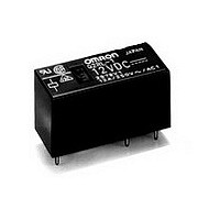
G2RL14DC24 Omron, G2RL14DC24 Datasheet - Page 4

G2RL14DC24
Manufacturer Part Number
G2RL14DC24
Description
Manufacturer
Omron
Type
Power Relayr
Datasheet
1.G2RL14DC24.pdf
(5 pages)
Specifications of G2RL14DC24
Relay Construction
Non-Latching
Contact Arrangement
SPDT
Coil Voltage Dc
24V
Coil Current
16.7mA
Contact Form
1 Form C
Voltage Rating (vdc)
300V
Voltage Rating (vac)
440V
Dropout Volt (min)
2.4VDCV
Coil Resistance
1.44kohm
Pick-up Voltage (max)
16.8VDC
Maximum Power Rating
3KVA
Operate Time
15ms
Contact Current Rating
12A
Contact Material
Ag(Cd Free)
Coil Suppression Diode
No
Push To Test Button
No
Led Indicator
No
Seal
Sealed
Product Height (mm)
15.7mm
Product Depth (mm)
12.7mm
Product Length (mm)
29mm
Operating Temp Range
-40C to 85C
Pin Count
5
Mounting Style
Through Hole
Termination Style
PC Pin
Lead Free Status / Rohs Status
Compliant
G2RL
Shock Malfunction
Electrical Endurance Data
Note: The results shown reflect values measured using very severe test conditions i.e., Duty: 1 s ON/1 s OFF.
Dimensions
Note: All units are in millimeters unless otherwise indicated.
4
1,000
1,000
G2RL-1 (A)-E
G2RL-1A(-H), G2RL-1A4
G2RL-1(-H), G2RL-14
G2RL-1A-E, G2RL-1A4-E
G2RL-1-E
G2RL-1
G2RL-1-H
G2RL-2
X'
Z'
Electrical endurance will vary depending on the test conditions. Contact your OMRON representative if you require more detailed information for the
electrical endurance under your test conditions.
NO contact
NC contact
130
Y
Y'
1,000
1,000
15.7 max.
(15.5)*
Unit: m/s
15.7 max.
(15.5)*
15.7 max.
(15.5)*
3.5
3.5
2
1,000
1,000
3.5
Z
X
0.5
0.5
Sample:
Number of Relays: 5pcs
Conditions:
Requirement:
Y
Y'
0.5
16 A at 250 VAC (cosφ=1)
16 A at 24 VDC
8 A at 250 VAC (cosφ=0.4)
8 A at 30 VDC (L/R=7 ms)
12 A at 250 VAC (cosφ=1)
12 A at 24 VDC
5 A at 250 VAC (cosφ=0.4)
5 A at 30 VDC (L/R=7 ms)
10 A at 250 VAC (cosφ=1)
10 A at 24 VDC
8 A at 250 VAC (cosφ=1)
8 A at 30 VDC
29 max.
(28.8)*
X
29 max.
(28.8)*
Shock direction
29 max.
(28.8)*
0.5
0.5
0.5
G2RL-14 DC12V
Shock is applied in ±X,±Y,±Z
directions three times each
with and without energizing the
Relays to check the number of
malfunctions.
None malfunction 100m/s
0.5
0.5
0.5
0.5
X'
Z
Z'
12.7 max.
(12.5)*
12.7 max.
(12.5)*
12.7 max.
(12.5)*
0.8
0.8
0.8
2
* Indicates average dimensions.
Terminal Arrangement/
Internal Connection
(Bottom View)
* Indicates average dimensions.
Terminal Arrangement/
Internal Connection
(Bottom View)
* Indicates average dimensions.
Terminal Arrangement/
Internal Connection
(Bottom View)
G2RL-2 (A)
1,000
1,000
5
1
8
1
X'
30,000 operations min.
30,000 operations min.
200,000 operation min. (normally open side operation)
10,000 operation min. (normally open side operation)
50,000 operations min.
30,000 operations min.
150,000 operation min. (normally open side operation)
20,000 operation min. (normally open side operation)
100,000 operations min.
50,000 operations min.
30,000 operations min.
30,000 operations min.
Z'
1
5
NO contact
2
NC contact
4
150
6
3
3
4
4
5
3
Y
Y'
1,000
1,000
(2.3)
7.5
(2.3)
7.5
(2.3)
Unit: m/s
7.5
Mounting Holes
(Bottom View)
Mounting Holes
(Bottom View)
Mounting Holes
(Bottom View)
2
1,000
1,000
Z
X
20
20
Sample:
Number of Relays: 5pcs
Conditions:
Requirement:
20
Y
Y'
3.5 3.5
X
Shock direction
3.5
5
Five, 1.3±0.1 dia.
holes
G2RL-24 DC12V
Shock is applied in ±X,±Y,±Z
directions three times each
with and without energizing the
Relays to check the number of
malfunctions.
None malfunction 100m/s
Four, 1.3±0.1 dia.
holes
Six, 1.3±0.1 dia.
holes
(2.5)
(2.5)
(2.5)
X'
Z
Z'
G2RL
2


