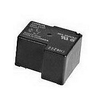
G8P1C4PDC24BYOMZ Omron, G8P1C4PDC24BYOMZ Datasheet

G8P1C4PDC24BYOMZ
Specifications of G8P1C4PDC24BYOMZ
Related parts for G8P1C4PDC24BYOMZ
G8P1C4PDC24BYOMZ Summary of contents
Page 1
Power PCB Relay G8PT • switching capacity in compact package. • Available with quick-connect contact terminals for easy load connecting with either QC or PCB coil terminals. • UL Class F coil insulation standard • Minimum ...
Page 2
Coil Data Rated Rated Coil voltage current resistance (VDC) (mA) 5 185 155 24 36 660 48 19 2,480 110 9 12,400 Note: The rated current and coil resistance are measured at a ...
Page 3
Characteristic Data Electrical service life SPST-NO Load current (A) Dimensions Unit: mm (inch) ■ Relays Open frame, PCB terminals SPDT Terminal arrangement/ Internal connections (Bottom view) Note: Terminal #4 is omitted on SPST-NO version. Power PCB Relay Load current ...
Page 4
Unit: mm (inch) Sealed/Ventable, PCB terminals Open frame, PCB with Quick Connect terminals G8PT 228 Power PCB Relay Terminal arrangement/ Internal connections (Bottom view) Note: Terminal #4 is omitted on SPST-NO version. Pin Dimensions large = 1.6 x 1.2; 1.2 ...
Page 5
Unit: mm (inch) Sealed/Ventable, PCB with Quick Connect terminals Flange mount Note: Allow air circulation within the sealed type G8PT by removing the ventilation nib from the cover after soldering and cleaning is complete. Terminal arrangement/ Internal connections (Bottom view) ...
Page 6
... Note: 1. The rated values approved by each of the safety standards (e.g., UL, CSA) may be different from the performance characteristics individually defined in this catalog. 2. For information on additional ratings not included in this catalog, contact your local Omron Representative the interest of product improvement, specifications are subject to change. ...
Page 7
... Seller within 30 days of receipt of shipment. III. PRECAUTIONS 1. Suitability THE BUYER’S SOLE RESPOINSIBILITY TO ENSURE THAT ANY OMRON PRODUCT IS FIT AND SUFFICIENT FOR USE IN A MOTORIZED VEHICLE APPLICATION. BUYER SHALL BE SOLELY RESPONSIBLE FOR DETERMINING APPROPRIATENESS OF THE PARTICULAR PRODUCT WITH RESPECT TO THE BUYER’ ...
Page 8
... THE OMRON PRODUCT IS PROPERLY RATED AND INSTALLED FOR THE INTENDED USE WITHIN THE OVERALL EQUIPMENT OR SYSTEM. Complete “Terms and Conditions of Sale” for product purchase and use are on Omron’s website at http://www.components.omron.com – under the “About Us” tab, in the Legal Matters section. ...


