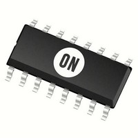
MC14538BDW ON Semiconductor, MC14538BDW Datasheet - Page 4

MC14538BDW
Manufacturer Part Number
MC14538BDW
Description
Monostable Multivibrator 3-18V Dual Precision
Manufacturer
ON Semiconductor
Datasheet
1.MC14538BCPG.pdf
(12 pages)
Specifications of MC14538BDW
Elements Per Chip
2
Logic Family
4000
Logic Type
Monostable Multivibrator
Package / Case
SOIC-16 Wide
Propagation Delay Time
600 ns, 300 ns, 220 ns
High Level Output Current
- 4.2 mA
Low Level Output Current
4.2 mA
Supply Voltage (max)
18 V
Supply Voltage (min)
3 V
Maximum Operating Temperature
+ 125 C
Minimum Operating Temperature
- 55 C
Mounting Style
SMD/SMT
Operating Supply Voltage
3.3 V, 5 V, 9 V, 12 V
Lead Free Status / Rohs Status
No RoHS Version Available
Available stocks
Company
Part Number
Manufacturer
Quantity
Price
Part Number:
MC14538BDW2G
Manufacturer:
ON/安森美
Quantity:
20 000
Part Number:
MC14538BDWG
Manufacturer:
ON/安森美
Quantity:
20 000
Company:
Part Number:
MC14538BDWR2G
Manufacturer:
TOSHIBA
Quantity:
2 000
Part Number:
MC14538BDWR2G
Manufacturer:
ON/安森美
Quantity:
20 000
Î Î Î Î Î Î Î Î Î Î Î Î Î Î Î Î Î Î Î Î Î Î Î Î Î Î Î Î Î Î Î Î Î
Î Î Î Î Î Î Î Î Î Î Î Î Î Î Î Î Î Î Î Î Î Î Î Î Î Î Î Î Î Î Î Î Î
Î Î Î Î Î Î Î Î Î Î Î Î Î Î Î Î Î Î Î Î Î Î Î Î Î Î Î Î Î Î Î Î Î
Î Î Î Î Î Î Î Î Î Î Î Î Î Î Î Î Î Î Î Î Î Î Î Î Î Î Î Î Î Î Î Î Î
4. The formulas given are for the typical characteristics only at 25_C.
5. Data labelled “Typ” is not to be used for design purposes but is intended as an indication of the IC’s potential performance.
6. The maximum usable resistance R
7. If C
SWITCHING CHARACTERISTICS (Note 4)
OPERATING CONDITIONS
Output Rise Time
Output Fall Time
Propagation Delay Time
Input Rise and Fall Times
Input Pulse Width
Retrigger Time
Output Pulse Width — Q or Q
Refer to Figures 8 and 9
Pulse Width Match between circuits in
External Timing Resistance
External Timing Capacitance
layout and surface resistance. Susceptibility to externally induced noise signals may occur for R
t
t
t
t
t
t
A or B to Q or Q
Reset to Q or Q
Reset
B Input
A Input
A, B, or Reset
the same package.
C
TLH
TLH
TLH
THL
THL
THL
t
t
t
t
t
t
C
C
C
X
PLH
PLH
PLH
PLH
PLH
PLH
X
X
X
X
= 0.1 mF, R
= (1.35 ns/pF) C
= (0.60 ns/pF) C
= (0.40 ns/pF) C
= (1.35 ns/pF) C
= (0.60 ns/pF) C
= (0.40 ns/pF) C
> 15 mF, use discharge protection diode per Fig. 11.
= 0.002 mF, R
= 0.1 mF, R
= 10 mF, R
, t
, t
, t
, t
, t
, t
PHL
PHL
PHL
PHL
PHL
PHL
= (0.90 ns/pF) C
= (0.36 ns/pF) C
= (0.26 ns/pF) C
= (0.90 ns/pF) C
= (0.36 ns/pF) C
= (0.26 ns/pF) C
X
X
X
= 100 kW
Characteristic
= 100 kW
= 100 kW
X
= 100 kW
L
L
L
L
L
L
+ 33 ns
+ 20 ns
+ 20 ns
+ 33 ns
+ 20 ns
+ 20 ns
L
L
L
L
L
L
+ 255 ns
+ 132 ns
+ 87 ns
+ 205 ns
+ 107 ns
+ 82 ns
X
is a function of the leakage of the capacitor C
(C
L
= 50 pF, T
http://onsemi.com
[(T
Symbol
MC14538B
1
t
t
t
– T
t
t
PLH
t
100
t
TLH
THL
PHL
WH
R
C
A
r
WL
t
, t
T
rr
X
X
= 25_C)
f
2
,
,
)/T
4
1
]
V
Vdc
5.0
5.0
5.0
5.0
5.0
5.0
5.0
5.0
5.0
5.0
10
15
10
15
10
15
10
15
10
15
10
15
10
15
10
15
10
15
10
15
10
15
10
15
10
15
5
5
5
−
−
DD
X
, leakage of the MC14538B, and leakage due to board
0.91
0.92
0.93
Min
170
198
200
202
9.3
9.4
9.5
5.0
90
80
−
−
−
−
−
−
−
−
−
−
−
−
−
−
−
−
−
−
0
0
0
−
−
−
0
X
> 1 MW..
All Types
(Note 5)
No Limit
10.14
0.965
± 1.0
± 1.0
± 1.0
9.86
0.98
0.99
Typ
100
100
300
150
100
250
125
300
210
212
214
1.2
0.4
50
40
50
40
95
85
45
40
10
−
−
−
−
−
−
−
−
No Limit
(Note 6)
(Note 7)
± 5.0
± 5.0
± 5.0
Max
0.05
10.5
10.6
10.7
1.03
1.04
1.06
200
100
200
100
600
300
220
500
250
190
230
232
234
1.0
0.1
80
80
15
5
4
−
−
−
−
−
−
Unit
ms
ms
kW
mF
ns
ns
ns
ns
ms
ns
ns
ms
%
−
s


