Output ..................................................................................................................................................................................................2-bit quadrature code
Closed Circuit Resistance .......................................................................................................................................................................... 3 ohms maximum
Contact Rating ................................................................................................................................................................................................ 1 mA @ 5 VDC
Insulation Resistance ....................................................................................................................................................................100 megohms @ 250 VDC
Dielectric Withstanding Voltage
Electrical Travel..................................................................................................................................................................................................... Continuous
Contact Bounce (15 RPM) .........................................................................................................................................................................5.0 ms maximum**
RPM (Operating) .............................................................................................................................................................................................. 60 maximum**
Operating Temperature Range ...................................................................................................................................... -30 °C to +70 °C (-22 °F to +158 °F)
Storage Temperature Range ......................................................................................................................................... -40 °C to +85 °C (-40 °F to +185 °F)
Humidity ............................................................................................................................................................... MIL-STD-202, Method 103B, Condition B
Vibration .......................................................................................................................................................................................................................... 30 G
Shock ............................................................................................................................................................................................................................ 100 G
Rotational Life ...................................................................................................................................................................................30,000 cycles minimum
Switch Life .........................................................................................................................................................................................20,000 cycles minimum
IP Rating ..........................................................................................................................................................................................................................IP 40
Mechanical Angle .........................................................................................................................................................................................360 ° continuous
Torque
Shaft Side Load (Static) ............................................................................................................................................................... 2.04 kgf (4.5 lbs.) minimum
Weight ............................................................................................................................................................................................ 5 gm (0.17 oz.) maximum
Terminals ................................................................................................................................................................................ Printed circuit board terminals
Hardware ...................................................................................................................... One fl at washer and one mounting nut supplied with each encoder
Switch Type ................................................................................................................................................................... Contact Push ON Momentary SPST
Power Rating (Resistive Load) ..................................................................................................................................................................... 10 mA at 5 V DC
Switch Travel ......................................................................................................................................................................................................0.5 ± 0.2 mm
Switch Actuation Force ...................................................................................................................................................... 610 ± 306 gf (8.47 ± 4.24 oz.-in.)
Model
Terminal Confi guration
Detent Option
Standard Shaft Length
Shaft Style
Switch Confi guration
Resolution
1 Metal knurled shaft with no switch is available in 15, 20 and 30 mm shaft lengths.
*RoHS Directive 2002/95/EC Jan 27, 2003 including Annex.
**Devices are tested using standard noise reduction fi lters. For optimum performance, designers should use noise reduction fi lters in their circuits.
Specifi cations are subject to change without notice.
Customers should verify actual device performance in their specifi c applications.
How To Order
Electrical Characteristics
Environmental Characteristics
Mechanical Characteristics
Switch Characteristics
Metal knurled shaft with push momentary switch is available in 15 and 20 mm shaft lengths.
Sea Level ............................................................................................................................................................................................... 300 VAC minimum
Contact Bounce............................................................................................................................................... 10~55~10 Hz / 1 min. / Amplitude 1.5 mm
Running ...................................................................................................................................................................... 50 to 200 gf.cm (0.68 to 2.7 oz.-in.)
Mounting...................................................................................................................................................................... 10.2 kgf.cm (8.83 lb.-in.) maximum
Soldering Condition
4 = PC Pin Horizontal/Rear Facing
0 = No Detents (12, 18, 24 pulses)
1 = 18 Detents (18 pulses)
2 = 24 Detents (12, 24 pulses)
3 = 12 Detents (12 pulses)
15 = 15.0 mm
20 = 20.0 mm
25 = 25.0 mm
30 = 30.0 mm
F = Metal Flatted Shaft
K = Metal Knurled Shaft 1
S = Push Momentary Switch
N = No Switch
0012 = 12 Pulses per 360 ° Rotation
0018 = 18 Pulses per 360 ° Rotation
0024 = 24 Pulses per 360 ° Rotation
Wave Soldering..................................................................................... Sn95.5/Ag2.8/Cu0.7 solder with no-clean fl ux: 260 °C max. for 3-5 seconds
Hand Soldering .................................................................................................................................................................................Not recommended
Features
■
■
■
■
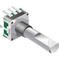
PEC11 Series - 12 mm Incremental Encoder
Push switch option
Compact, rugged design
High reliability
Metal bushing/shaft
PEC11 - 4 0 20 F - S 0012
Quadrature Output Table
A Signal
B Signal
CW
OFF
D
ON