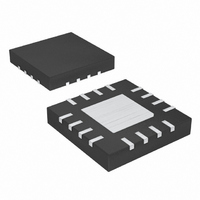
MAX4691EGE+T Maxim Integrated Products, MAX4691EGE+T Datasheet - Page 12

MAX4691EGE+T
Manufacturer Part Number
MAX4691EGE+T
Description
IC MULTIPLEXER 8X1 16QFN
Manufacturer
Maxim Integrated Products
Series
4000r
Datasheet
1.MAX4694EBET.pdf
(21 pages)
Specifications of MAX4691EGE+T
Function
Multiplexer
Circuit
1 x 8:1
On-state Resistance
70 Ohm
Voltage Supply Source
Single, Dual Supply
Voltage - Supply, Single/dual (±)
2.7 V ~ 11 V, ±2.7 V ~ 5.5 V
Operating Temperature
-40°C ~ 85°C
Mounting Type
Surface Mount
Package / Case
16-QFN Exposed Pad
Lead Free Status / RoHS Status
Lead free / RoHS Compliant
Low-Voltage 8:1 Mux/Dual 4:1 Mux/Triple SPDT/
Quad SPDT in UCSP Package
The MAX4691–MAX4694 are low-voltage CMOS analog
ICs configured as an 8-channel multiplexer (MAX4691),
two 4-channel multiplexers (MAX4692), three SPDT
switches (MAX4693), and four SPDT switches
(MAX4694). All switches are bidirectional.
The MAX4691/MAX4692/MAX4693 operate from either
a single +2V to +11V power supply or dual ±2V to
±5.5V power supplies. When operating from ±5V sup-
plies they offer 25Ω on-resistance (R
R
The MAX4694 operates from a single +2V to +11V sup-
ply. Each switch has rail-to-rail signal handling, fast
switching times of t
1nA leakage current.
All digital inputs are 1.8V logic-compatible when oper-
ating from a +3V supply and TTL-compatible when
operating from a +5V supply.
The MAX4691 and MAX4692 include address pins that
allow control of the multiplexers. For the MAX4691, pins
Table 1. Truth Table/Switch Programming
X = Don’t care
1. EN is not present on the MAX4694.
2. C is not present on the MAX4692 and MAX4694.
12
ON
EN
1
0
0
0
0
0
0
0
0
______________________________________________________________________________________
flatness, and 3Ω max matching between channels.
1
C
X
0
0
0
0
1
1
1
1
ADDRESS BITS
2
B
X
0
0
1
1
0
0
1
1
ON
Detailed Description
= 80ns, t
A
X
0
1
0
1
0
1
0
1
All switches open
OFF
MAX4691
= 50ns, and a low
X-X0
X-X1
X-X2
X-X3
X-X4
X-X5
X-X6
X-X7
Digital Inputs
ON
), 3.5Ω max
All switches open
X-X0, Y-Y0
X-X1, Y-Y1
X-X2, Y-Y2
X-X3, Y-Y3
X-X0, Y-Y0
X-X1, Y-Y1
X-X2, Y-Y2
X-X3, Y-Y3
MAX4692
A, B, C determine which switch is closed. The two 4-1
muxes in the MAX4692 are controlled by the same
address pins (A and B). (Table 1)
The MAX4693 and MAX4694 offer SPDT switches in
triple and quadruple packages. In the MAX4693, each
switch has a unique control input. The MAX4694 has
two digital control inputs: A (for switches “W” and “Y”)
and B (for switches “X” and “Z”). (Table 1)
The MAX4691–MAX4694 construction is typical of most
CMOS analog switches. V+ and V-* are used to drive
the internal CMOS switches and set the limits of the
analog voltage on any switch. Reverse ESD-protection
diodes are internally connected between each analog
signal pin and both V+ and V-. If any analog signal
exceeds V+ or V-, one of these diodes will conduct.
* V- is found only on the MAX4691/MAX4692/MAX4693.
ON SWITCHES
All switches open
X-X0, Y-Y0, Z-Z0
X-X1, Y-Y0, Z-Z0
X-X0, Y-Y1, Z-Z0
X-X1, Y-Y1, Z-Z0
X-X0, Y-Y0, Z-Z1
X-X1, Y-Y0, Z-Z1
X-X0, Y-Y1, Z-Z1
X-X1, Y-Y1, Z-Z1
Applications Information
MAX4693
Power-Supply Considerations
W-W0, X-X0,
W-W1, X-X0,
W-W0, X-X1,
W-W1, X-X1,
W-W0, X-X0,
W-W1, X-X0,
W-W0, X-X1,
W-W1, X-X1,
Y-Y0, Z-Z0
Y-Y1, Z-Z0
Y-Y0, Z-Z1
Y-Y1, Z-Z1
Y-Y0, Z-Z0
Y-Y1, Z-Z0
Y-Y0, Z-Z1
Y-Y1, Z-Z1
MAX4694
—
Overview


