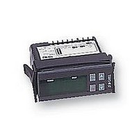
IR32W10000 CAREL, IR32W10000 Datasheet - Page 6

IR32W10000
Manufacturer Part Number
IR32W10000
Description
10WX3782
Manufacturer
CAREL
Datasheet
1.D-C73L.pdf
(9 pages)
Specifications of IR32W10000
Thermocouple Type
PT100
Operating Temperature Max
600°C
Operating Temperature Min
-99°C
Output Voltage Max
250VAC
Accuracy
± 0.5%
Accuracy %
0.5%
Approval Bodies
CE
Display
Digital LED
Parameter Table
Code
St1
St2
C0
P1
P2
P3
C4
C5
C6
C7
C8
C9
C10
C11
C12
C13
P14
C15
C16
C17
C18
C19
C21
C22
C23
C24
P25
P26
P27
P28
C29
C30
C31
C32
C33
C50
C51
Note: Prim = Primary functions, FM = Function Modes, Adv = Advanced functions
Set-Point 1
Set-Point 2 (Function Modes 6, 7, 8, 9)
Function Mode
Hysteresis of SP1
Hysteresis of SP2 (Function Modes 3, 4, 5, 7, 8, 9)
Dead-Band (Function Modes 3, 4, 5)
Compensation Coefficient - NTC only (see operation manual)
Control action in Function Mode 4. 0 = Prop (P), 1 = Prop + Integ (PI)
Delay between on routines of two different outputs
Minimum time between on routines of the same output
Minimum off time of the same output
Minimum on time of the same output
Status of outputs with probe(temperature) alarm :
Output rotation (Function Modes 1, 2, 6, 7, 8 and Models W & Z only)
Cycle Time of proportional modes (P and PI)
Probe type: 0 = 4 - 20mA, 1 = 0 - 20mA or 0 = K T/c, 1 = J T/c
Probe calibration or offset
Minimum value for scaling of analogue inputs
Maximum value for scaling of analogue inputs
Probe response time (noise filter)
Temperature units: 0 = o C, 1 = o F
Ambient compensation of 2nd probe - NTC only (see operation manual)
Minimim Set-Point (SP1) limit (depends on probe type)
Maximim Set-Point (SP1) limit (depends on probe type)
Minimim Set-Point (SP2) limit (depends on probe type)
Maximim Set-Point (SP2) limit (depends on probe type)
Low absolute alarm set-point
High absolute alarm set-point
Alarm hysteresis
Alarm delay
Alarm relay status with Digital Input (DI) (C0 = 5 only):
Note: Whenever DI opens Er3 message occurs & buzzer sounds.
Digital input 2 (IRDR models only). Options as for C29
Status of output relays with Digital input (see C10)
Address of unit for serial comms. connection
Do not modify this parameter
Activation of Keypad (KP) and Remote Control Unit (RC) :
Code to activate Remote Control Unit
0 = all relays de-energised
1 = all relays energised
2 = Direct action relays energised, all others de-energised
3 = Reverse action relays energised, all others de-enegised
0 = no rotation
1 = rotation of 2 out of 4 outputs (model Z only)
2 = 2 + 2 rotation (Compressor on outputs 1 & 3, model Z only)
3 = 2 + 2 DWM rotation (model Z only)
0 = Non active input
1 = Immediate alarm - all relays de-energise, automatic reset on clear
2 = Immediate alarm - all relays de-energise, manual reset(mute) on clear
3 = delayed alarm (P28) - all relays de-energise, manual reset(mute) on clear
4 = All alarm relays inactive with DI open (-- -- --) flashes
0 = KP off, RC on (code 22)
1 = KP on, RC on (code 22)
2 = KP off, RC off
3 = KP on, RC off
4 = KP off, RC on (code 77)
Function
Default
Value
20
40
2
2
2
2
0.5
0
5
0
0
0
0
0
20
0
0
0
100
5
0
0
min probe -99 to C22
max probe C21 to 999
min probe -99 to C24
max probe C23 to 999
min probe -99 to P26
max probe P25 to 999
2
60
0
0
0
1
0
0
0
Range
see spec.
see spec.
1 to 9
0.1 to 99.9
0.1 to 99.9
0 to 99.9
-2.0 to 2.0
0 or 1
0 to 999 secs
0 to 15 mins
0 to 15 mins
0 to 15 mins
0 to 3
0 to 3
0.2 to 999 secs
0 or 1
-99 to 99.9
-99 to C16
C15 to 999
1 to 14
0 or 1
1 to 4
0.1 to 99.0
0 to 120 mins
0 to 4
0 to 4
0 to 3
1 to 16
0 or 1
0 to 4
120
Parameter Access
Prim FM
X
X
X
X
X
X
X
X
X
X
X
X
X
X
X
X
X
Page 4
Adv
X
X
X
X
X
X
X
X
X
X
X
X
X
X
X
X
X
X
X
X
X
X
X
X
X
X
X
X
X
X
X
X
X
X
X


