MAX336CWI Maxim Integrated Products, MAX336CWI Datasheet
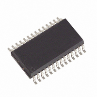
IC MULTIPLEXER 16X1 28SOIC

MAX336CWI

Manufacturer Part Number
MAX336CWI
Description
IC MULTIPLEXER 16X1 28SOIC
Manufacturer
Maxim Integrated Products
Datasheet

Specifications of MAX336CWI

Function
Multiplexer
Circuit
1 x 16:1
On-state Resistance
400 Ohm
Voltage Supply Source
Single, Dual Supply
Voltage - Supply, Single/dual (±)
4.5 V ~ 30 V, ±4.5 V ~ 20 V
Current - Supply
1µA
Operating Temperature
0°C ~ 70°C
Mounting Type
Surface Mount
Package / Case
28-SOIC (0.300", 7.50mm Width)
Lead Free Status / RoHS Status
Contains lead / RoHS non-compliant

Available stocks

Company
Part Number
Manufacturer
Quantity
Price
Part Number:
MAX336CWI
Manufacturer:
MAXIM
Quantity:
2
Part Number:
MAX336CWI
Manufacturer:
MAXIM/美信
Quantity:
20 000
Part Number:
MAX336CWI+
Manufacturer:
Maxim
Quantity:
2 025
Part Number:
MAX336CWI+T
Manufacturer:
MAXIM/美信
Quantity:
20 000
The MAX336/MAX337 are monolithic, CMOS analog
multiplexers (muxes). The 16-channel MAX336 is
designed to connect one of 16 inputs to a common out-
put by control of a 4-bit binary address. The dual,
8-channel MAX337 is designed to connect one of eight
inputs to a common output by control of a 3-bit binary
address. Both devices can be used as either a mux or
a demux. On-resistance is 400Ω (max), and the devices
conduct current equally well in both directions.
These muxes feature extremely low off leakages (less
than 20pA at +25°C) and on-channel leakages (less than
50pA at +25°C). The new design offers guaranteed low
charge injection (3.5pC typical) and electrostatic dis-
charge (ESD) protection greater than 2000V, per method
3015.7. These improved muxes are pin-compatible
upgrades for the industry-standard DG506 and DG507.
The MAX336/MAX337 operate from a single +4.5V to
+30V supply or from dual ±4.5V to ±20V supplies. All
control inputs (whether address or enable) are TTL
compatible (0.8V to 2.4V) over the full specified temper-
ature range and over the ±4.5V to ±18V supply range.
For free samples & the latest literature: http://www.maxim-ic.com, or phone 1-800-998-8800
________________________Applications
19-1193; Rev 0; 4/97
Rail-to-Rail is a registered trademark of Nippon Motorola Ltd.
_____________________Pin Configurations/Functional Diagrams/Truth Tables
_______________General Description
TOP VIEW
NO16
NO15
NO14
NO13
NO12
NO11
NO10
GND
N.C.
N.C.
NO9
N.C.
N.C. = NO INTERNAL CONNECTION
V+
A3
10
11
12
13
14
1
2
3
4
5
6
7
8
9
Precision Data Acquisition
Precision Signal Routing
Test Equipment
DIP/SO/SSOP
Low-Leakage, CMOS Analog Multiplexers
MAX336
________________________________________________________________ Maxim Integrated Products
25
24
23
19
18
17
16
15
28
27
26
22
21
20
COM
V-
NO8
NO5
NO4
NO3
NO1
EN
A0
A1
NO7
NO6
NO2
A2
NO10
NO11
NO12
NO13
NO14
NO15
NO16
NO1
NO2
NO3
NO4
NO5
NO6
NO7
NO8
NO9
MAX336 16-CHANNEL SINGLE-ENDED MULTIPLEXER
V+
A0
16-Channel/Dual 8-Channel,
CMOS DECODERS/DRIVERS
A1
V-
A2
Ordering Information continued at end of data sheet.
* Contact factory for dice specifications.
____________________________Features
______________Ordering Information
MAX336CPI
MAX336CWI
MAX336CAI
MAX336C/D
<400Ω (max) On-Resistance
<500ns Transition Time
<10Ω On-Resistance Match
<20pA NO-Off Leakage Current at +25°C
3.5pC Charge Injection
+4.5V to +30V Single Supply
±4.5V to ±20V Dual Supplies
Plug-In Upgrade for Industry-Standard
DG506/DG507
Bidirectional Rail-to-Rail
TTL/CMOS-Logic Compatible
>2000V ESD Protection, per Method 3015.7
PART
A3
GND
EN
TEMP. RANGE
COM
0°C to +70°C
0°C to +70°C
0°C to +70°C
0°C to +70°C
LOGIC “0” = V
Continued at end of data sheet.
A3
X
0
0
0
0
0
0
0
0
1
1
1
1
1
1
1
1
®
A2
X
0
0
0
0
1
1
1
1
0
0
0
0
1
1
1
1
Signal Handling
AL
A1
X
0
0
1
1
0
0
1
1
0
0
1
1
0
0
1
1
0.8V, LOGIC “1” = V
MAX336
PIN-PACKAGE
28 Plastic DIP
28 Wide SO
28 SSOP
Dice*
A0
X
0
1
0
1
0
1
0
1
0
1
0
1
0
1
0
1
EN
0
1
1
1
1
1
1
1
1
1
1
1
1
1
1
1
1
AH
SWITCH
NONE
ON
10
11
12
13
14
15
16
1
2
3
4
5
6
7
8
9
2.4V
1

Related parts for MAX336CWI

MAX336CWI Summary of contents

Page 1

... Single Supply ±4.5V to ±20V Dual Supplies Plug-In Upgrade for Industry-Standard DG506/DG507 Bidirectional Rail-to-Rail TTL/CMOS-Logic Compatible >2000V ESD Protection, per Method 3015.7 ______________Ordering Information PART MAX336CPI MAX336CWI MAX336CAI MAX336C/D Ordering Information continued at end of data sheet. * Contact factory for dice specifications GND NO1 NO2 ...

Page 2

Low-Leakage, CMOS Analog Multiplexers ABSOLUTE MAXIMUM RATINGS Voltage Referenced ............................................................................-0.3V, 44V GND .........................................................................-0.3V, 25V Digital Inputs, A_, EN_, NO, COM (Note 1).............................................(V- - 0.3V) to (V+ + 0.3V) or 30mA (whichever occurs first) Continuous Current ...

Page 3

Low-Leakage, CMOS Analog Multiplexers ELECTRICAL CHARACTERISTICS—Dual Supplies (continued) (V+ = +15V -15V, GND = 0V PARAMETER SYMBOL INPUT Input Current with I AH Input Voltage High Input Current with I AL Input Voltage Low SUPPLY Power-Supply ...

Page 4

Low-Leakage, CMOS Analog Multiplexers ELECTRICAL CHARACTERISTICS—Single Supply (V+ = +12V 0V, GND = 0V +2.4V PARAMETER SYMBOL SWITCH Analog Signal Range V COM On-Resistance R ON DYNAMIC Transition Time ...

Page 5

Low-Leakage, CMOS Analog Multiplexers ____________________________Typical Operating Characteristics (continued +25°C, unless otherwise noted.) A ON-RESISTANCE vs. V COM 700 600 V± = ±5V 500 400 V± = ±15V V± = ±10V 300 200 100 V± = ±20V 0 -20 ...

Page 6

Low-Leakage, CMOS Analog Multiplexers ______________________________________________________________Pin Description PIN MAX336 MAX337 13, 14 — 2 4–11 — NO16-NO9 — 4–11 NO8B–NO1B 12 12 14–17 — — 15, 16, 17 A2, A1 ...

Page 7

Low-Leakage, CMOS Analog Multiplexers ______________________________________________Test Circuits/Timing Diagrams +15V NO2–NO15 A0 MAX336 +2.4V GND 50 -15V +15V NO1A–NO8A, MAX337 +2.4V GND 50 -15V Figure 2. Transition Time ...

Page 8

Low-Leakage, CMOS Analog Multiplexers _________________________________Test Circuits/Timing Diagrams (continued) +15V V+ +2.4V EN NO1–NO16 A0 A1 MAX336 A2 A3 GND V- 50 -15V Figure 4. Break-Before-Make Interval +15V R S NO1–NO16 EN MAX336 CHANNEL SELECT ...

Page 9

Low-Leakage, CMOS Analog Multiplexers _________________________________Test Circuits/Timing Diagrams (continued) +15V 10nF +2. NO2 NO16 A0 MAX336 GND 10nF V OUT OFF ISOLATION = 20log V IN Figure 6. Off Isolation ...

Page 10

Low-Leakage, CMOS Analog Multiplexers ________Pin Configurations/Functional Diagrams/Truth Tables (continued) TOP VIEW COMB NO8B 4 25 NO7B 24 5 MAX337 NO6B 6 23 NO5B 7 22 NO4B 8 21 NO3B 9 ...

Page 11

Low-Leakage, CMOS Analog Multiplexers __Ordering Information (continued) PART TEMP. RANGE MAX336EPI -40°C to +85°C MAX336EWI -40°C to +85°C MAX336EAI -40°C to +85°C MAX336EJI -40°C to +85°C MAX336MJI -55°C to +125°C MAX337CPI 0°C to +70°C MAX337CWI 0°C to +70°C MAX337CAI 0°C ...

Page 12

... Maxim cannot assume responsibility for use of any circuitry other than circuitry entirely embodied in a Maxim product. No circuit patent licenses are implied. Maxim reserves the right to change the circuitry and specifications without notice at any time. 12 __________________Maxim Integrated Products, 120 San Gabriel Drive, Sunnyvale, CA 94086 (408) 737-7600 © 1997 Maxim Integrated Products Printed USA ...

Related keywords