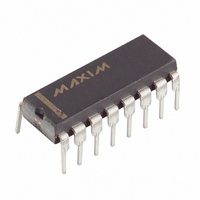
MAX355EPE Maxim Integrated Products, MAX355EPE Datasheet

MAX355EPE
Specifications of MAX355EPE
Available stocks
Related parts for MAX355EPE
MAX355EPE Summary of contents
Page 1
... Max Input Leakage at +25°C (5nA at +85°C) No Power-Up Sequencing Required TTL and CMOS-Logic Compatibility ______________Ordering Information PART MAX354CPE MAX354CWE MAX354C/D MAX354EPE MAX354EWE MAX354MJE MAX355CPE MAX355CWE MAX355C/D MAX355EPE MAX355EWE MAX355MJE * Dice are tested Contact factory for availability. TOP VIEW A1 A2 GND V+ NO5 NO6 NO7 NO8 TEMP ...
Page 2
Fault-Protected Analog Multiplexers ABSOLUTE MAXIMUM RATINGS (Voltages referenced to GND, unless otherwise noted.) V+ ...........................................................................-0.3V to +44V V- ............................................................................+0.3V to -44V V+ to V-...................................................................-0.3V to +44V Digital Inputs.........................................(V+ + 0.3V) to (V- - 0.3V) Input Overvoltage with Mux Power On ...
Page 3
Fault-Protected Analog Multiplexers ELECTRICAL CHARACTERISTICS (continued) (V+ = +15V -15V, GND = 0V PARAMETER SYMBOL FAULT Output Leakage Current (with Overvoltage) Input Leakage Current (with Overvoltage) Input Leakage Current (with Power Supplies Off) DIGITAL LOGIC INPUT ...
Page 4
Fault-Protected Analog Multiplexers ELECTRICAL CHARACTERISTICS (continued) (V+ = +15V -15V, GND = 0V PARAMETER SYMBOL DYNAMIC (cont’d) COM-Off Capacitance C COM(OFF) COM-On Capacitance C COM(ON) Setting Time (Note 5) t SETT Note 1: When ...
Page 5
Fault-Protected Analog Multiplexers ____________________________Typical Operating Characteristics (continued +25°C, unless otherwise noted.) A SUPPLY CURRENT vs. TEMPERATURE 1000 V+ = +15V V- = -15V V = +5V EN 100 10 1 0.1 -75 -50 - TEMPERATURE ...
Page 6
Fault-Protected Analog Multiplexers ______________________________________________Test Circuits/Timing Diagrams +15V V+ NO1 A2 A1 NO2-NO7 A0 MAX354 NO8 COM GND V- 50 -15V +15V V+ NO1B A1 A0 NO1A-NO4A NO4B MAX355 COMB GND V- 50 -15V Figure ...
Page 7
Fault-Protected Analog Multiplexers _________________________________Test Circuits/Timing Diagrams (continued) +15V +2.4V EN NO1–NO8 A0 MAX354 GND V- 50 -15V Figure 3. Break-Before-Make Interval MAX354 CHANNEL A1 ...
Page 8
Fault-Protected Analog Multiplexers _________________________________Test Circuits/Timing Diagrams (continued) +15V NO1 NO8 MAX354 COM GND 10nF -15V OFF ISOLATION = 20log Figure 5. Off Isolation +15V V+ A2 NO1 CHANNEL A1 ...
Page 9
Fault-Protected Analog Multiplexers Figure 10 shows the condition of an off channel with V+ and V- present. As with Figures 8 and 9, either an N- channel or a P-channel device will be off for any input voltage from -40V ...
Page 10
Fault-Protected Analog Multiplexers The channel-to-channel switching time is typically 180ns, with about 100ns of break-before-make delay. This 100ns break-before-make delay prevents the input-to-input short that would occur if two input chan- nels were simultaneously connected to the output ...
Page 11
Fault-Protected Analog Multiplexers Table 2a. Typical Off-Isolation Rejection Ratio Frequency 100kHz One Channel Driven 100dB Test Conditions 20Vp-p at the tabulated frequency 1.5kΩ between OUT and ground 0V. L 20Vp 20log ...
Page 12
... Maxim cannot assume responsibility for use of any circuitry other than circuitry entirely embodied in a Maxim product. No circuit patent licenses are implied. Maxim reserves the right to change the circuitry and specifications without notice at any time. 12 __________________Maxim Integrated Products, 120 San Gabriel Drive, Sunnyvale, CA 94086 (408) 737-7600 © 1996 Maxim Integrated Products ...


